
Table of contents
- Introduction
- 1. Relevance of the topic <
- 2. The purpose and objectives of the study, the planned results
- 3. The Flying Saw
- 3.1 Principle of operation of the Flying Saw
- 4. Modernization proposal
- Conclusions
- List of sources
Introduction
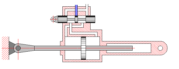
Figure 1 – The principle of operation of a hydraulic amplifier with an output link in the form of a two-rod hydraulic cylinder
Pipes with a diameter of 6 to 660 mm are produced on continuous pipe-electric welding units (TES). The main technological operations in the production of electric welding pipes are forming of a pipe billet, welding and calibration (reduction) of a welded pipe. These technological operations are combined into one cycle and are carried out continuously.
There are various versions of pipe-cutting machines for pipe-welding mills. In some cases, the rolled pipe is fed to the cutting tool, in others, the cutting tool is fed to the rolled pipe to make the cut. Circular saws are used as a cutting tool, since when using scissors or guillotines, after cutting, the ends of the pipes remain curved. Straightening the ends of pipes is difficult, therefore, in pipe finishing these ends are cut off, that is, using a saw, in addition to a clean cut, also helps to reduce metal losses and improve the quality of products.
A continuously moving pipe cutting machine is called a "volatile" one, since it allows cutting without stopping the pipe rolling. Flying machines differ in the drive of the longitudinal movement of the carriage on which the cutting tool is mounted. The drive often consists of an electric motor, which can be connected to the carriage by means of a gear wheel and a rack, or by means of a helical transmission, carrying out longitudinal movement of the carriage. However, these types of transmissions have a number of disadvantages.1. The relevance of the topic
Along with coal mining and ferrous metallurgy, metallurgical production, and in particular the production of hot-rolled pipes, is an important industry. One of the main problems in any production is the continuity of production, increasing the efficiency of machines, reducing the number of technological operations and, as a result, reducing production costs. In the production of hot-rolled pipes, pipe-welded mills with pipe cutting machines are used equal sections of different lengths. Automation of the pipe-cutting machine is possible to ensure the continuity of pipe production at the pipe-welding mill.
2. The purpose and objectives of the study, the planned results
The purpose of this work is to improve the drive of the cutting machine of the pipe welding mill by using a volumetric hydraulic drive. Since they have a number of advantages over other types of gears:
• high developed force with small dimensions;
• ease of speed and force control;
• smooth and silent running;
• limitation of the maximum load on the actuator provided by safety valves;
• the ability to adjust the position of the rod;
• possibility to select the maximum piston load;
• easy installation and connection;
• durability.
Work tasks.:
- Investigation of current versions of pipe-cutting machines of pipe-welding mills..
- Description and evaluation of the new operating principle.
- Formulation of a mathematical model.
- Assessment of the quality of the new calculation approach, formulation of recommendations.
The object of research: A volumetric hydraulic drive, as a means for moving a cutting machine.
The subject of the study: a method for automating the necessary calculations to update the work to current capabilities and requirements.
As part of the master's work, it is planned to obtain relevant knowledge on the following issues.
- Obtaining software to simplify settlement activities.
- Determining the applicability of this approach to real-world tasks.
- The possibilities of modifying current systems.
- The possibility of an accurate assessment of the results obtained.
In the experimental part of the master's thesis, it is planned to use software methods for calculating the rational parameters of the hydraulic drive system of the pipe-welding mill cutting machine.
3. A Flying Saw.
The flying saw is a continuously moving pipe cutting machine that allows cutting without stopping the pipe rolling. Flying machines differ in the drive of the longitudinal movement of the carriage on which the cutting tool is mounted. The drive often consists of an electric motor, which can be connected to the carriage by means of a gear wheel and a rack, or by means of a helical transmission, carrying out longitudinal movement of the carriage.
3.1 The Principle of operation of a Flying Saw.
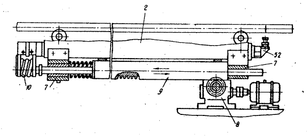
Figure 3.1 – Longitudinal displacement drive
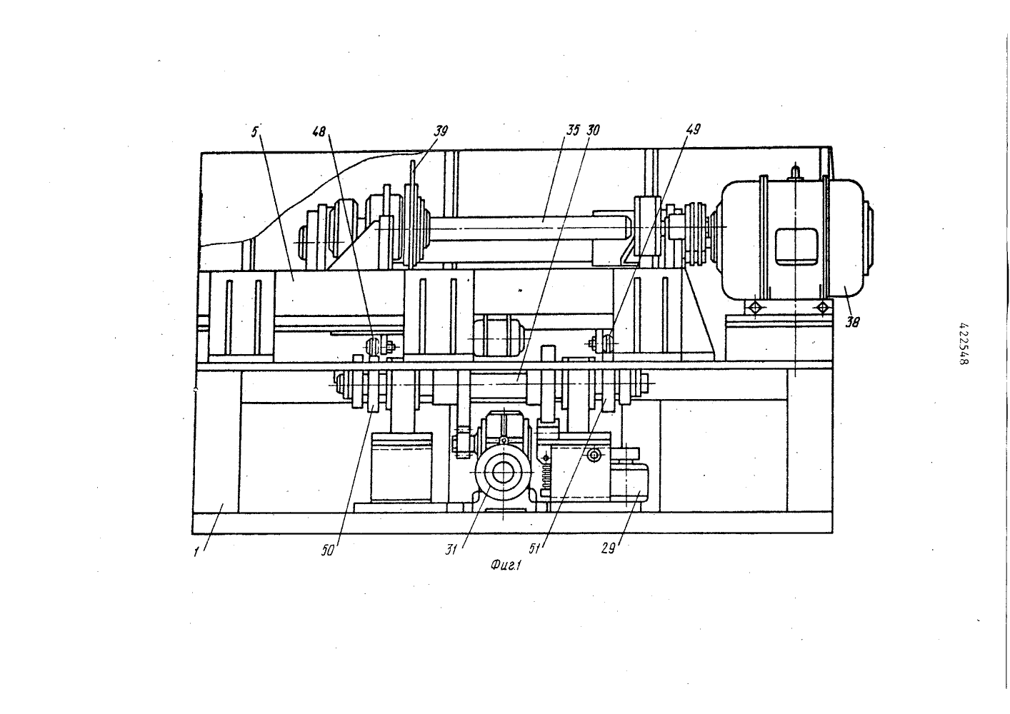
Figure 3.2 – General view of the Flying Saw
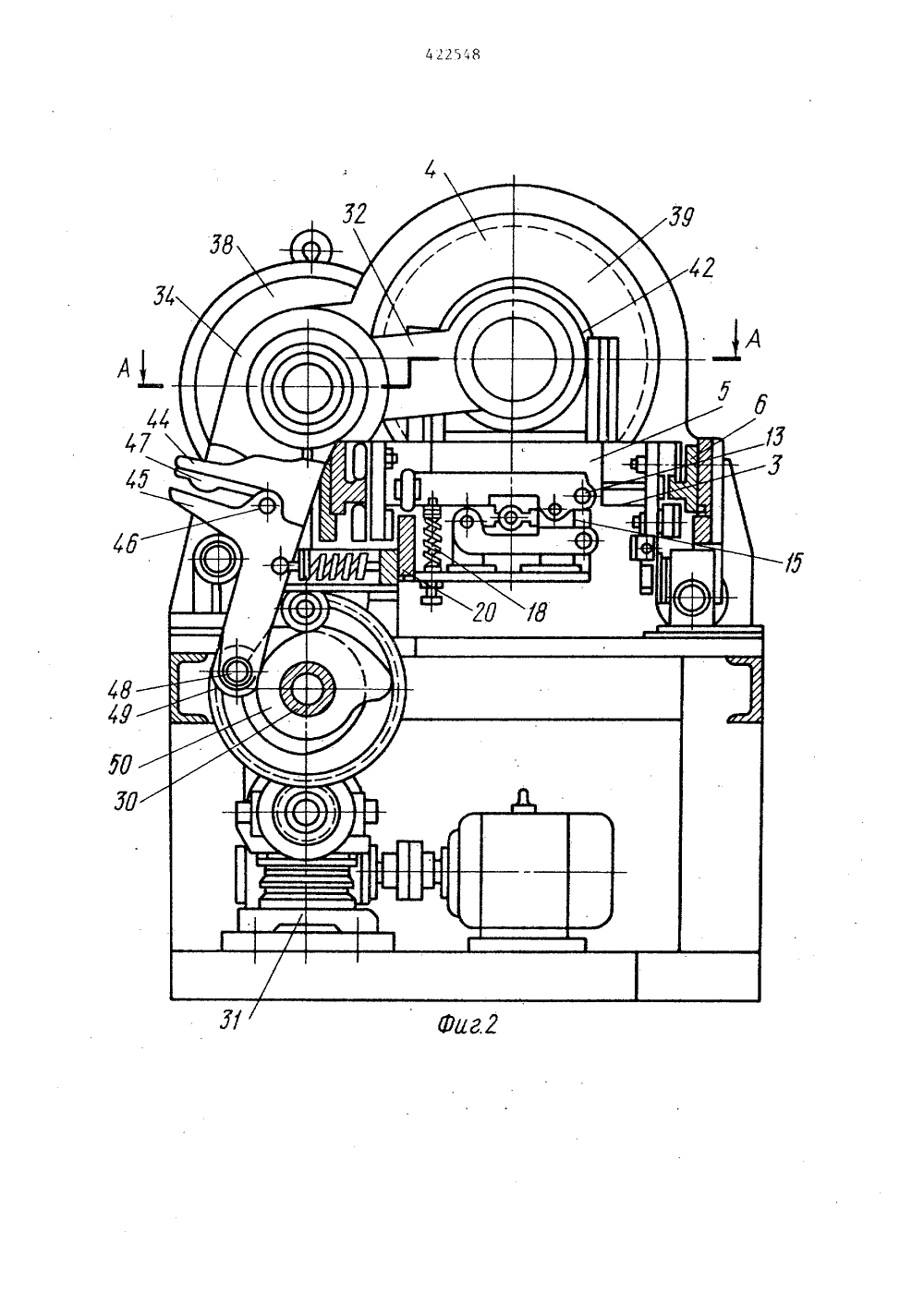
Figure 3.3 – General view of the Flying Saw from the side
The Saw works as follows.
The pipe is fed into the working area of the flying saw. The photo sensor 53 fixes the joint of the pipes and gives the command to turn on the drive 8 of the carriage 5. The carriage, moving at a higher speed than the product, catches up with the joint and when the cutter and the joint are combined, the pneumatic actuator 29 turns on, which outputs the roller 27 from the groove of the disc 28 and simultaneously moving the rod 25 removes the lever stop 24 from under the guide bar 20. As a result, the counterweight, descending downwards under the action of a spring 18, presses the profiled sponges 11 and 12 to the product. Due to the friction force between the product and the jaws, the carriage drive 8 acquires the speed of the product, and since the carriage moves the housing 41 in its guide posts 43 with a floating sleeve 40 rotating in it with a cutting mill fixed to it, the milling cutter moves along the shaft 35 with the speed of movement of the product.
When the drive shaft 30 is rotated 1/2 turn from the drive cams 50 and 51, the milling cutter is fed to cut the product, and with further rotation of the cams, the milling cutter enters its initial position.
The carriage is disconnected from the product by the cam 23, and the return to the starting position is carried out by the roller 27, which simultaneously holds the guide bar 20 is in a position that ensures the uncompressed state of the carriage clamps.
With an increase in the speed of the product relative to the speed of movement of the carriage by the drive 8, the spring-loaded toothed rail 9, moving in the guides 7, enters the inductor coil 10, thereby changing the voltage in the field windings of the electric drive through the amplifier circuit (not shown) to equalize product speeds and rails.
When using a flying saw to cut products into measured lengths, the size of which is repeated continuously, the sensor 52 is turned off, and the sensor 53 is removed at the desired length of the cut products and when passing the end of the product, it includes drives 8, 29 and 31, which ensure the cutting process of the product and the return of the system to the starting position.
When using a saw to cut products in continuously varying sizes, the drive 29 is connected to the circuit of the tracking sensor in the path function, a software device interacting with the signal, working according to the method of comparing signals.
4. Modernization proposal
In order to increase reliability and safety, to implement the necessary load capacity and overload resistance, as well as to implement a smoother, faster and more accurate carriage movement, it is proposed to use a hydraulic cylinder as a drive for the longitudinal movement of the carriage on which the cutting tool is mounted.
The saw works as follows. Pipe 1 is fed into the working area of the flying saw. The control signal is applied to a proportional hydraulic distributor, which controls the hydraulic cylinder of the longitudinal movement of the carriage 2. The working fluid enters the piston cavity of the hydraulic cylinder. The rod pushes the carriage 3, which moves on rollers 4 along guides 5 along the rolling line. The carriage, moving at a higher speed than the product, catches up with the intended cutting location and when the saw speed and pipe speed are combined, the clamping hydraulic cylinders 9 are triggered. Due to the friction force between the product and the clamps, the carriage drive acquires the speed of the product. The hydraulic cylinder of the circular saw movement 6 moves the electric motor 7 with a circular saw 8 for cutting. After cutting, the circular saw returns to its original position, the product is unclenched and the hydraulic cylinder of the longitudinal movement of the carriage returns the carriage to its original position. The cycle repeats.
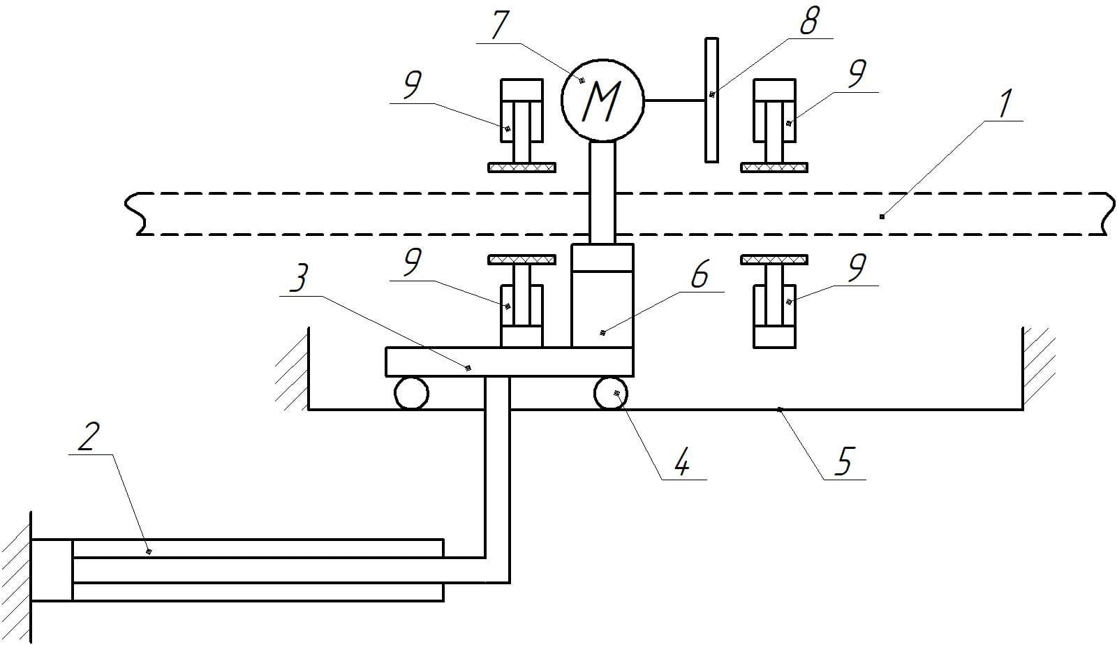
Figure 3.1 – Longitudinal displacement drive
Conclusions
This work is aimed at solving the scientific and technical task of modernizing the system the drive of the cutting machine of the pipe-welding mill and the determination of the rational parameters of its operation.
The use of the proposed method will lead to an increase in the service life, increase the efficiency of the machine and a more rational use of economic resources.
Main conclusions, scientific and practical results of the work:
- Evaluation of the hydraulic drive capabilities.
- Determining the applicability of this approach to real-world tasks.
- Possibility of modification of the current pipe-welding mills.
When writing this essay, the master's thesis has not yet been completed. The full text of the work and materials on the topic can be obtained from the author or his supervisor.
List of sources
List of sources
- A.V. Stoyanov. Patent SU 422548, 1986.
- V.I. Golubev. Power adjustable hydraulic drive in power engineering. A textbook on the course "Volumetric hydraulic drive". Moscow, 1989, 107 p.
- Sveshnikov V. K. Machine hydraulic drives: Handbook – 6th ed. reprint. and additional – St. Petersburg: Polytechnic, 2015. – 627 p.
- V.K. Sveshnikov, A.A. Usov. Machine hydraulic drives: Handbook. – M.: Mechanical engineering, 1982. – 464 p.
- Geyer V.G., Dulin V.S., Zarya A.N. Hydraulics and hydraulic drive: Textbook for universities. — 3rd ed., revised and additional. — M.: Nedra, 1991. — 331 p.
- V. M. Yakovlev, V. A. Melnikov. Methodological guidelines for the course work on the discipline "Hydraulic drive and automation equipment". – Donetsk: DONNTU, 2018. – 68 p .
- International Metallurgical Research