
An abstract on the topic of the graduation work
Content
- Introduction
- Scope, purpose, indexing, classification of rolls
- The design and principle of operation of two-roll crushers
- Conclusion
- List of sources
Introduction
Construction machines are now an integral part in any field indirectly or directly related to construction. They make it possible to improve and control the quality of construction, speed up construction time, and facilitate human labor.Construction machines are now an integral part in any field indirectly or directly related to construction. They make it possible to improve and control the quality of construction, speed up construction time, and facilitate human labor.
A large amount of stone materials is consumed in construction every year: crushed stone, gravel and sand. Most of these materials are used for the preparation of concrete. Extraction of sand and gravel is carried out in natural deposits by mechanical or hydraulic means, and crushed stone from natural stone by crushing blasted rocks. The extracted stone materials are processed at stone crushing and washing and sorting plants, and then delivered to the consumer in the form of a finished product of standard quality.
In many industries of building materials, ceramic, glass, cement and others, roller crushers are widely used, designed for large, medium, small and fine grinding of materials of low and medium strength, removal of stony inclusions from clay, etc.
Scope, purpose, indexing, classification of roller crushers
Roller crusher is a processing crushing equipment equipped with rolls with toothed segments fixed on them, having the shape of a polyhedron rigidly mounted on a shaft. Roller crushers are widely used for fine, medium and fine grinding of various rocks, food products and chemical materials (clay materials, chamotte, quartz, spar, etc.).
The principle of operation of these mills consists in grinding the material mainly by crushing, partially by abrasion, impact or bending between two parallel cylindrical rolls rotating towards each other at the same speed.
For brittle and soft materials (for example, coal, salt), toothed roller crushers are used. They capture pieces that are only 1.5-4 times smaller than the diameter of the roll.
Crushers with smooth and grooved rolls are usually used for crushing materials of medium strength (up to cj = 150 MPa); crushers with toothed rolls – for crushing coal and similar materials of low strength (up to cj = 80 MPa). The size of the crushing product of a roller crusher depends both on the size of the outlet gap between the rolls and on the type of surface of the working bodies. In world practice, roller crushers are used, as a rule, at the final stages of crushing (medium and fine crushing).
A significant disadvantage of roller crushers is the intensive and uneven wear of the working surfaces of the rolls (bandages) when processing durable and abrasive rocks. The bandage wears out mainly in the middle part of the roll, which makes it impossible to maintain a stable size of the outlet slot along its entire length. In addition, roller crushers have a relatively low specific productivity.
Roller crushers are classified as follows.
According to the purpose and shape of the work surface:
- for fine, fine and medium crushing of materials – with a smooth surface of the rolls, with longitudinal semicircular recesses on one of the rolls;
- for large crushing of clay materials with toothed rolls;
- for medium and fine crushing of clay materials and stone removal – with one smooth and another grooved rolls and with rolls having a helical surface.
According to the method of installing roller bearings:
- with one pair of movable and one pair of fixed bearings;
- with fixed bearings;
- with movably mounted bearings on two rolls.
By the number of rolls in the crushers:
- with one;
- с двумя;
- with four.
According to the drive device:
- with gear drive and cardan shafts;
- with gear drive;
- with belt drive
- with gear drive and belt drive
The design and principle of operation of two-roll crushers
Crushers with one movable roll (Fig. 2, a) are the most common. In almost all existing designs of roller crushers, one of the rolls is mounted in movable bearings sliding along the guides. The bearings are held in place by springs compressed with special bolts. When foreign objects enter, the springs shrink under increasing load, the gap between the rolls increases and the foreign body falls out of the crusher. Further, under the action of springs, the bearings with the roller return to their original position.
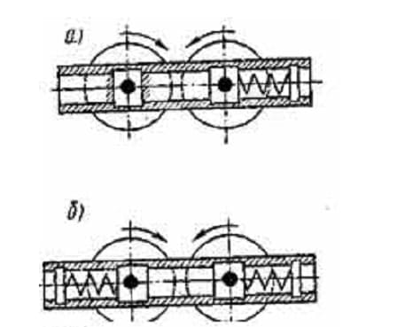
Figure 2. Diagrams of crushers
In crushers with movably mounted bearings (Fig. 2, b), both pairs of bearings are movable, rest against springs, and therefore, when foreign objects enter, both rolls move apart and allow foreign bodies to pass through. Since the rolls, diverging, move in the opposite direction at the same speed, and the inertia forces arising from the movement of the rolls are mutually balanced, then crushers of this type work relatively calmly and they are called balanced. However, due to the complexity of the design and high cost, this type of crushers has not been widely used.
The crusher consists of two rolls rotating towards each other and mounted on shafts 2, supported by bearings. One pair of bearings 3 is fixed to the frame, and the second pair 4 can move along the frame. At the same time, the housings of this pair of bearings are constantly pressed against the stops by springs 5. Replaceable steel gaskets are placed between the stops and the bearing housings, regulating the size of the gap between the rolls.
The rolls are driven by an electric motor (or transmission) via a belt drive. In the presence of a gear train, the teeth of the second pair are made elongated in height so that it is possible to ensure engagement when the movable roll departs.
The "traditional" two-roll crusher, widespread until recently (Fig. 8). The pulley 2 of the crusher is rotated by an electric motor, then through a single-stage gearbox closed by a casing 8, rotation is transmitted to the first grooved roller 3, whose bearing housings are fixed to the frame 1 of the crusher. The bearings 7 of the second smooth roll 4 are pressed against the stop by shock-absorbing springs 5 and can move by compressing the springs, increasing the gap between the rolls and passing an indestructible object. Rotation from the first (driving) shaft is transmitted to the second (driven) roller using gears with elongated teeth, allowing a change in the center distance between the shafts of the rolls. The gears rotate in an oil bath and are covered by a casing 6.
Recently, constructive solutions have appeared in which each roll is driven by an electric motor or through a gearbox 3 and cardan shafts 4.
Figure 8. Two-roll crusher with grooved and smooth rolls.
The roller crusher (fig. 9) has two rolls, one of which is smooth, the other is grooved. The bearings of one of the rolls are attached to the crusher body 5, the bearings of the other to a movable frame 3 connected by a hinge 4 to the body. In the upper part, the body and frame are interconnected by a safety mechanism 1, consisting of a system of rods and springs that allow adjusting the gap between the rolls, as well as allowing the rolls to diverge when an unbreakable object hits. In this case, the roll, together with the movable frame and the electric motor mounted on it, rotates around the hinge, and the gap between the rolls increases. After passing through an indestructible object, the springs return the roll to its original position. The force required to crush the material is provided by pre-compression of the springs.
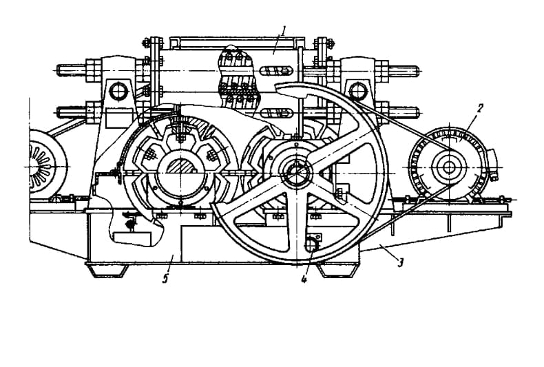
Figure 9. Two-roll crusher with separate roller drive.
The DDZ-6 crusher consists of the following elements (Figure 11): 1-an outlet slot adjustment mechanism, 2-rolls lined with toothed bands, 3-a drive electric motor, 4.5-bearing supports, 6-a frame, 7-a receiving funnel, 8-a safety mechanism. The drive is carried out by a V-belt transmission from a separately installed electric motor. The rotation is transmitted to the drive shaft, and then through the synchronizer to the slow–moving rolls - movable and stationary.
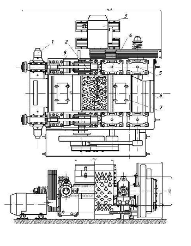
Figure 11 Roller crusher DDZ-6
Initially, the design of the shock-absorbing device of two-roll gear crushers consisted of one or more (their number reached nine in one block) steel cylindrical springs on each side. However, when operating crushers with such shock-absorbing devices, it was found that during the operation of the crusher, the shaft of the movable roll may be skewed due to either unequal spring stiffness or one-sided (off-center) loading of the crusher's power supply. Shaft misalignment worsens the technological performance of the crusher, increases power consumption and can lead to breakdowns.
To avoid misalignment of the movable roll, an attempt was made to connect the bearing housings of the movable roll with one rocker arm to the installation of a common shock-absorbing spring. However, this version of the shock-absorbing device has not been developed due to a significant increase in the mass of the crusher.
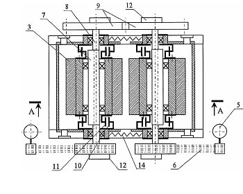
In the crushers DDZ-1M, DDZ-2M and DDZ-4M, which were mass-produced in the 60s of the last century (Fig. 14), the maximum stroke of the movable roll was 40, 55 and 60 mm, respectively, which was not enough to ensure reliable operation of the machine.
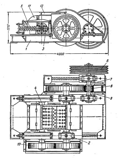
Figure 14 – Double-roll gear crusher DDZ-4 [2]: 1 – frame; 2, 3 – bearing housing; 4 – roller; 5 – spring; 6 – pulley; 7 – shaft; 8 – gear; 9 – wheel; 10 – synchronizer; 11 – casing; 12 - funnel
The main reason for such a small stroke was explained by the fact that for each crusher, the stroke value was taken such that, with the greatest gap between the rolls, the gear wheel of the rotary drive of the movable roll did not get out of engagement. This is caused by the design of the roll rotation synchronizer, which used gears with an increased tooth length. Therefore, if the stroke was not enough to pass an unbreakable piece and it wedges between the rolls, then the safety pin installed in the hub of the flywheel pulley was cut off. In order to avoid overloading the springs when the rolls are jammed, the stroke of the movable bearings is limited by a special stop available in the bed of the pressing device.
In the future, the shock-absorbing device of two-roll crushers, as well as the design of the synchronizer, were continuously improved. Figure 14 shows one of the variants of the shock-absorbing device used in a crusher of the DDZ type with an increased stroke of the movable roll.
Cylindrical steel springs were used in shock-absorbing devices of two-roll crushers of the DDZ or DDZE-9×9 type, but in a number of crushers (some modifications of the DDZ, DDZE-15×12 crushers, etc.) disc springs were used [4]. So, in crushers of the DDZ type of the 70s of the last century, a shock-absorbing device (Fig. 15) [4] included two rods 12, one end of which was mounted on the housing 13 of the rolling roller bearing, and the second end was provided with a toothed rail 14 in contact with the gear wheel 15, on the axis of which there was a cam clutch 16. Disc springs 17 were used in the device. The parallel movement of the movable roller was provided by two sprockets 18 and a chain 19.
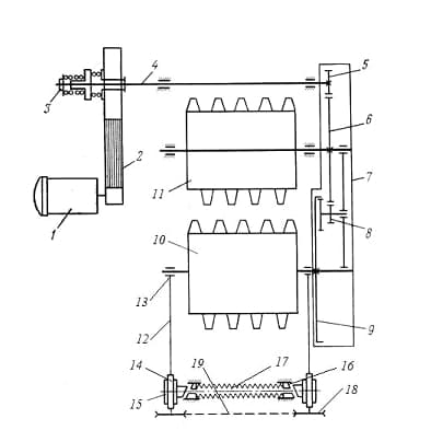
Figure 15 – Kinematic diagram of a two–roll toothed DDZ crusher: 1 - electric motor; 2 – V–belt transmission; 3 – safety clutch; 4 – drive shaft; 5 – 9 – synchronizer elements (transmission mechanism); 10 – movable roll; 11 – stationary roll; 12 - thrust; 13 - movable roll bearing housing; 14 - gear rack; 15 – gear wheel; 16 – cam clutch; 17 – spring; 18 – sprocket; 19 - chain
When a non-crushing material gets between the rolls, a shock-absorbing device is triggered, and the movable roll 10 moves away. Bearing housings 13, sliding along round guides, move the rails 14, which rotate the gears 15 of the spring shock absorber and compress the springs 17. The unbreakable material passes between the rolls, and the springs 17 return the entire roll 10. If the roller 10 has moved away by more than 200 mm, then the bearing housing 13 acts on a limit switch mounted on one of the racks, which turns off the electric motor. The nominal compression value of the springs 17 of the shock absorber should be 35 mm on each side. With a decrease in the degree of compression, the crusher becomes more sensitive to large pieces of coal, as well as to unbreakable objects [4].
Figure 16 shows the modern design of the shock-absorbing device of the DDZ crusher [6].
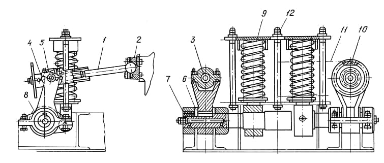
Figure 16 – Shock–absorbing device of modern DDZ crushers: 1 – screw; 2, 5 – cover; 3 – trunnion; 4 - lever; 6 – bar; 7 – shaft; 8 – bearing; 9 – spring; 10 - sprocket; 11 – chain; 12 - nut
The shock–absorbing device includes a screw 1, which is connected on one side by means of a cover 2, to the body of the deflecting roll, on the other - to a trunnion 3 mounted on a lever 4, using a cover 5. The lever is attached by a bar 6 to the shaft 7, which is mounted in bearings 8. Between the bearings on the shaft using The cams connected to the springs 9 are fixed to the dowels. An asterisk 10 is installed at the end of the screw, the rotation of which regulates the size of the discharge gap between the rolls. Simultaneously with the sprocket, the screw 1 rotates, which moves the deflecting roll through the cover 2. The parallel movement of the deflecting roll is ensured by the fact that the sprockets 10 are interconnected by a chain 11. Pre-compression of the springs 9 is carried out using nuts 12.
The advantages of spring shock absorbers include:
- constructive simplicity;
- the ability to withstand huge loads;
- the weak influence of the environment on the operation of shock absorbers.
However, due to great efforts (5...10 kN per 1 cm roll) spring blocks of mechanical shock-absorbing devices of gear crushers are complex, massive and bulky. Therefore, all operations for setting up the device (tightening springs, changing the size of the gap) become quite time-consuming.
Hydropneumatic shock-absorbing devices allow you to quickly adjust the size of the outlet slit, change the stiffness of the elastic element over a wide range, and also ensure synchronous departure of the bearing housings of the movable roll during the off-center passage of an unbreakable object. Reliably protecting the crusher from breakdowns, the hydropneumatic "outside" practically does not wear out.
The use of hydropneumatic shock absorbers makes it possible to eliminate most of the disadvantages of mechanical shock absorbers, as well as increase the reliability of roller crushers.
Thus, the authors of the invention [5], proposed a hydropneumatic amortizer (Fig. 17), including hydraulic cylinders 1 with pistons 2, covers 3, a hydro-pneumatic accumulator 4, a throttle valve 5, toothed rails 7 and toothed wheels 8 mounted on the shaft 9. To ensure fast and shock-free departure of the mobile roller 6 of the crusher when hit by an unbreakable object, pistons 2 are made with ledges entering the corresponding recesses of the covers of hydraulic cylinders 1 and forming a closed cavity. The throttle 5 is installed on a pipeline connecting the cavities A of the hydraulic cylinders 1 to the atmosphere.
When an indestructible object hits, the roll 6 moves away, moving the pistons 2, which displace the liquid from the hydraulic cylinders 1 into the battery 4 filled with nitrogen. After passing an unbreakable object, the roll 6 quickly returns to its previous position under the action of compressed nitrogen, which squeezes the liquid into the hydraulic cylinders 1. In this case, a certain volume of air is locked and compressed in the cavity B between the ledges of the pistons 2 and the recesses of the covers 3, which prevents an impact.
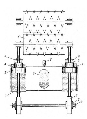
Figure 17 - Hydropneumatic shock absorber of a two-roll crusher [7]: 1 – hydraulic cylinder; 2 – piston; 3 – lid; 4 – hydropneumatic accumulator; 5 - throttle valve; 6 - movable roller; 7 - toothed rack; 8 - gear wheel; 9 – shaft
In the design of a hydropneumatic shock-absorbing device, it is advisable to combine the safety function and the possibility of adjusting the size of the gap. Figure 18 shows the hydraulic circuit of a two-roll crusher with these properties.
A pump 2 with a constant flow direction sucks liquid from the tank 1 and pumps it into the hydraulic cylinder 5 through a distributor 3 and a hydraulic lock 4. In position A of the distributor 3, the liquid enters the left cavity of the hydraulic cylinder 5, moving the piston to the right (the distance between the rolls decreases). In position B of the distributor 3, the pressure line connects to the right cavity of the hydraulic cylinder 5, (the distance between the rolls increases). In the middle position of the distributor 3, the pressure line is locked, and both outlets A and B are connected to the tank 1, so that the hydraulic lock 4 locks the cavities of the hydraulic cylinder. Amortization of the movable roll is carried out using a hydropneumatic accumulator 6. In case of overload of the system, the working fluid is drained through the safety valve 7.
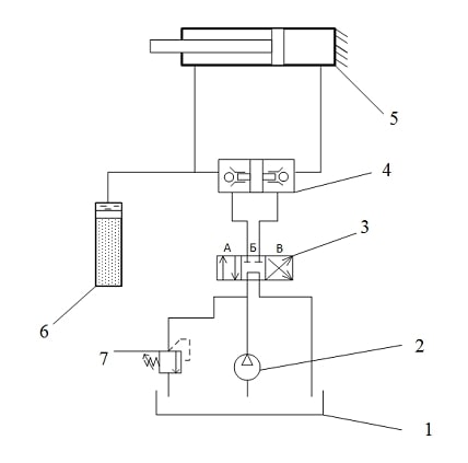
Figure 18 - Hydraulic circuit for damping and adjusting the distance between the rolls of a two-roll crusher
The scheme in question ensures low noise operation of the shock-absorbing device, the installation becomes less dimensional, the hydraulic system simultaneously performs a shock-absorbing function and the function of changing the distance between the rolls, retains the shock-absorbing ability.
This design solution will significantly increase the reliability and efficiency of using roller crusher depreciation. At the same time, in order for the shock absorbers to work correctly, in order to avoid mechanical damage and distortions, it is necessary to ensure synchronization of the operation of both hydraulic cylinders. Figures 19 and 20 show two options for synchronizing the operation of hydraulic cylinders [4].
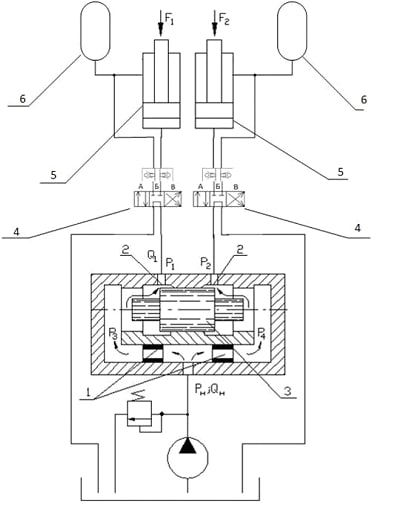
Figure 18 - Synchronization scheme using a throttle flow divider: 1 - balanced hydraulic throttles; 2 - adjustable hydraulic throttles; 3 - plunger; 4 - hydraulic valves; 5 - hydraulic cylinders; 6 - batteries
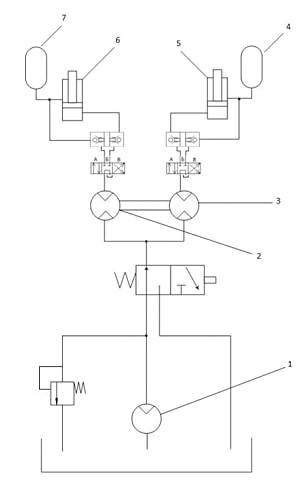
Figure 19 - Synchronization scheme with two rotary hydraulic machines: 1 - pump; 2, 3 – rotary hydraulic machines; 4, 7 – hydropneumatic accumulator; 5, 6 –hydraulic cylinders
Conclusion
In the work [2] the designs of crushers can be analyzed and the following conclusions are made. A common disadvantage for all crushers is the high specific metal consumption and energy consumption of structures. The main trend in the improvement of crushers, as can be seen from the analysis of patent materials and literature sources, is the development of energy-saving tools and technologies. The main direction of increasing the efficiency of machinery and machine complexes is to increase productivity and reduce operating costs to maintain their operability, which can be achieved through modernization and creation of new machines while reducing their weight and overall dimensions.
Figure 1 shows the design diagram of a crusher with cycloidal roll motion [3]. The kinematic scheme of the RO drive is implemented using the James planetary mechanism, which contains a central gear of internal engagement, a carrier and a satellite (planetary) of external engagement, rolling inside the crown gear. The driver receives rotation from the drive motor. The working body of the roller crusher is coaxially connected to the satellite and performs planetary motion with it, while the vertices describe one or another hypocycloid.
List of sources
- Bogdanov, V.S. Classification of roller crushers / V.S. Bogdanov, I.S. Yavorskaya – Direct text // Energy-saving technological complexes and equipment for the production of building materials. Interuniversity collection of articles. Volume Issue XIV. Belgorod State Technological University named after V.G. Shukhov; edited by V.S. Bogdanov. Belgorod, 2015. pp. 152-154.
- Rabat, O.J. Identification of the main directions in the design of working bodies of crushing machines based on the analysis of patent information / O.J. Rabat, A.N. Salmanova // Bulletin of KazATK. – 2018. - № 1 (104). – Pp. 98-105.
- Rabat O.J., Li S.V., Murzakhmetova U.A., Nurgalieva M.R. Design features of a roller crusher with complex movement of working bodies // Transport, mining and construction engineering: science and production. – 2018. – No.1. – pp. 38-44.
- Kondrakhin, V.P. Analysis of structures of shock-absorbing devices of two-roll gear crushers / V.P. Kondrakhin, S.L. Bukin, A.A. Berezin
- Pat. 93037015 RF, IPC F03B13/12. Coastal power plant / Handel E.G. - Publ. 1996.02.10.
- Moldavanov O.I. Metrological support of pipeline construction. M. : Nedra, 1984. - 224 p. : ill.
- Ostromensky P.I., Aksenov V.A., Atapin V.G. Mathematical modeling in mechanical engineering: Textbook. Novosibirsk: NSTU, 1993. 81 p.
- Pat. 2089747 RF, MKI F03B13/12. Electric energy generator for converting the energy of sea waves / Miung Shik Im. - Publ. 1997.09.10.