
Abstract
Content
- Introduction
- 1. Relevance of the topic
- 2. Purpose and objectives of the study, planned results
- 3. Features and problems of dosed discharge of steel into casting molds from ladles equipped with stop systems
- 3.1 Design features of ladles used in foundries
- 3.2 The main causes of emergency situations during the operation of casting ladles of various capacities equipped with stop systems
- 3.3 Prospects for equipping foundry laths with gate valves instead of locking devices
- 4. Selection of a rational design scheme for the electromechanical gate valve drive and its adaptation to use on casting ladles of various capacities
- 4.1 Selection of a basic sample of an electromechanical drive for a gate valve of a casting ladle
- 4.2 Development of a mechanical drive design for casting ladles with a capacity of 5 - 10 tons
- Conclusion
- References
Introduction
In the foundry production of domestic and foreign large machine-building plants, dosed supply of liquid metal into molds is carried out using ladles equipped with stoppers consisting of a metal rod protected from high temperatures by refractory coils and a plug screwed onto its threaded lower end.
In the ferrous metallurgy, from 1974 to 1985, all steel-pouring ladles were transferred to stopless steel casting, which involved the use of a sliding or rotary valve equipped with a set of refractory elements, which included a ladle pouring nozzle, for controlled drainage of liquid metal installed on the outer surface of the ladle bottom. , two (sometimes three) plates and a collector glass.
Over the past years, more than 50 designs of gate valves have been used in global steelmaking practice, differing in the type of movement of the refractory plate closing the channel, the method of pressing it, and the type of drive.
1. Relevance of the topic
At the same time, to date, despite the success achieved in the use of gate systems in the conditions of steelmaking shops of metallurgical enterprises, on ladles with a capacity of 5 - 50 tons, operated in foundries at both domestic and foreign machine-building plants, attempts have been made to replace locking devices rolling bolts were not successful.
For Russian machine-building plants, the Shiber
company (Moscow) and NPP Vulkan-TM
(Tula) proposed variants of gate devices adapted for use on casting ladles with a
capacity of 10 tons. Their industrial testing, unfortunately, did not give the expected results, since a simple transfer of experience accumulated during the implementation
of gate devices on buckets with a capacity of over 100 tons, in this case, turned out to be insufficient for a number of reasons that require careful assessment and understanding.
We are talking about the type of gate drive, the method of pressing its refractory plates, as well as the procedure for servicing and operating this filling system in the specific conditions of a foundry. Therefore, work related to the study of the possibility of converting casting ladles with a capacity of 5 to 50 tons to stopless casting of steel is of great scientific and practical importance.
2. Purpose and objectives of the study, planned results
The goal of the research is to develop gate valve systems intended for use on casting ladles of various capacities.
To achieve this goal, the following main tasks were considered:
- Causes of emergency situations during the operation of casting ladles of various capacities, equipped with locking devices;
- An analysis of the results of previously conducted research work related to the transfer of foundry ladles to steel casting using gate valves was carried out;
- New design solutions have been proposed for equipping casting ladles with sliding gates equipped with a mechanical drive, instead of stoppers;
- A methodology has been developed for calculating the energy-power parameters of the mechanical drive of a bucket gate;
- An experimental verification of the correctness of the adopted technical solutions and the correctness of the calculated dependencies used was carried out;
- Recommendations for industrial application of the research results have been developed;
The object of the study is gate valve systems intended for use in foundries.
Subject of research: design and power parameters of bucket valve systems equipped with electromechanical drives.
3. Features and problems of dosed discharge of steel into casting molds from ladles equipped with stop systems
3.1 Design features of ladles used in foundries
In the foundries of machine-building plants, depending on the type of products produced and the weight of the workpieces used in the form of forgings and castings, electric arc furnaces with a charge of 5 to 50 tons are in operation. In accordance with this, the tonnage of casting ladles required to receive liquid steel is determined from the melting furnace and its subsequent pouring into flasks or molds.
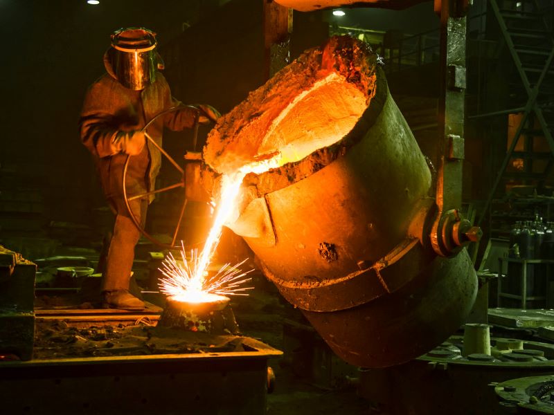
Figure 1.1 – Foundry ladle
A foundry ladle (Fig. 1.1) is a metal container of a welded structure in the shape of an inverted truncated cone. The bucket body consists of a casing, a bottom, a drain sock, an edge bracket and elements of a trunnion belt - an upper stiffener, a trunnion plate and a lower stiffener.
The bucket casing is made from sheets welded together. A slight taper in the range from 1:12 to 1:7 has a positive effect on the durability of the lining, since with this shape it is easy to remove frozen slag residues and build-up, while the risk of damage to the lining is reduced. In addition, the tapered shape makes it easier to remove worn lining.
A stiffening ring is welded into the upper part of the casing, which gives the necessary rigidity to the casing and keeps the lining from falling out when the bucket overturns.
The axle belt, located in the middle part of the casing, is designed to relieve it from bending moments that occur on the axles when lifting a loaded bucket by crane. The elements of the axle belt, as well as the transition zone from the bottom to the casing, are the most loaded parts of the bucket, and the greatest stresses arise in them. Therefore, the reliable and durable operation of the bucket and its weight largely depend on the correct choice of their design and size.
The position of the axle axis along the height of the bucket is determined by safety regulations, according to which the center of gravity of a loaded bucket must be at least 200 mm below the axis of the axles. This arrangement of the axis around which the bucket is tilted will protect it from accidental tipping during transportation. In practice, the position of the center of gravity can differ greatly from the calculated one (due to improper laying of the lining, the presence of build-ups, etc.). If the center of gravity of a loaded bucket is located at a distance of less than 200 mm from the axle axis, then special devices must be provided on the bucket body to protect it from tipping over.
Bottom of the bucket. Flat and spherical bottoms of various types are used in casting ladles. In the zone of transition of the bottom into the casing, under the influence of the weight of the metal and lining, local stresses arise, the magnitude of which will be less, the smoother the transition is. Since in flat bottoms the interface with the casing is made at a right angle or with a slight rounding, the local stresses in the interface zone reach very large values, therefore the flat bottoms have to be made thicker, and, consequently, heavier than spherical bottoms of the same diameters, working under the same conditions. However, in small-capacity buckets, flat bottoms have become predominant. This is explained by the fact that it is much easier and cheaper to produce flat bottoms than spherical bottoms, and the relative weight reduction when producing small-sized spherical bottoms is relatively small.
Low-capacity casting ladles are equipped with one locking mechanism. On heavy-duty ladles used to produce castings weighing over 20 tons, the number of locking devices can reach four, which is due to the need to feed liquid steel into the mold simultaneously through several gates in order to reduce the duration of its filling.
3.2 The main causes of emergency situations during the operation of casting ladles of various capacities equipped with stop systems
The critical part of the stop-filling device is a refractory rod with a plug at the lower end. When pouring steel into a ladle, the plug experiences severe thermal shock. At the junction with the pouring nozzle, the plug often freezes , which is fraught with its separation from the metal rod and the occurrence of an emergency situation. During the flow of steel from the casting ladle, the plug is washed by it from all sides and undergoes intense erosion, as a result of which leakage of liquid metal occurs when the channel is closed. When the jet is blocked, a significant compressive load is applied to the plug, which contributes to the formation of chips and cracks. In Fig. Figure 1.2 shows a photograph of a locking rod with characteristic damage.

Figure 1.2 – Typical zones of damage to the stopper rod from the influence of various factors on the stopper plug during operation of the filling device
Thus, the complex of destructive factors acting on the rod and its plug is diverse, which quite often leads to disruption of the normal functioning of the stop casting device, and this ultimately leads not only to metal losses, but also to the risk of receiving defective castings due to violation required casting speed. This problem is especially acute during the operation of casting ladles equipped with several locking devices and used in the production of large mass castings, when at least one of the four locking devices malfunctions [1].
3.3 Prospects for equipping foundry laths with gate valves instead of locking devices
To eliminate the negative effects of factors identified during industrial testing of gate systems developed by Russian companies for small-tonnage casting ladles, a comprehensive analysis of the features of their operation and the selection of technical solutions that will best ensure compliance of the capabilities of the ladle gate with these features are necessary.
The main distinguishing features of the operating conditions of casting ladles, as noted earlier, are the need to move them by crane over considerable distances and the large number of required overlaps of the steel outlet channel, due to the order of placement on the work site and the sequence of filling prepared flasks or molds with liquid metal. In this regard, the drive of the casting ladle shutter must ensure the autonomy of the entire casting system and its ease of control, as well as the ability to close the steel outlet channel in the presence of a metal crust on its walls that forms while the ladle is moving from one mold to another. In addition, unlike the locking mechanism, which is manually actuated, the gate valve has a drive that requires an energy supply to it. Therefore, in the event of an emergency situation associated with an emergency shutdown of the power plant supplying it, the drive must provide the ability to complete the process of pouring metal into molds manually using special simple devices.
As is known, gate valves can be equipped with a hydraulic, pneumatic or electromechanical drive, shown schematically in Fig. 1.3. Each of these drives has its own advantages and disadvantages, which manifest themselves depending on the conditions of use, therefore, when choosing a drive scheme, preference is given to the one that best meets the production conditions of a particular steel foundry.

Figure 1.3 – Types of sliding bucket valve drives
Due to the small size and weight of the hydraulic cylinder, which is installed on the ladle only during casting, the hydraulic drive (Fig. 1.3, a) is convenient to use. However, hydraulic cylinders are not reliable enough at high temperatures and are dangerous in terms of fire. Elements of a hydraulic drive operating at an oil pressure of 10–12 MPa and above require particularly precise manufacturing and appropriate qualifications of operating personnel. For reliable operation of the hydraulic drive, a double reserve of supply oil stations is required. In order to eliminate metal losses due to ruptures of hoses and failure of oil stations, special backup devices for opening and closing the slide gate are required, for which emergency accumulators are used to shut off the gate channel.
The duration of moving the refractory plate from one extreme position to another using a hydraulic drive, depending on the capacity of the pouring ladle, is 3–8 s.
The pneumatic drive (Fig. 1.3 b) is powered by a workshop compressed air network with a pressure of 0.3 - 0.6 MPa and consists of a pneumatic cylinder, a pneumatic distributor and a transmission lever. The time it takes for the movable plate to move when the shutter is fully opened or closed is 3–5 s. The advantages of a pneumatic drive include:
- Simplicity of design, repair and maintenance;
- Ease of getting into working condition;
- Safety in operation compared to other types of drives;
- Ease of duplicating the general workshop compressed air network by installing reserve cylinders;
- Low capital costs for bucket equipment.
The disadvantages of this type of drive are the low accuracy of metal jet control due to the variability of the speed of movement of the pneumatic cylinder piston, as well as the need to insulate the workshop compressed air network at low temperatures.
The electromechanical drive (Fig. 1.3 c) includes an electric motor, a reduction gearbox and a low-speed gear transmission, which can be spur or bevel. In valves with translational movement of a refractory plate that covers the outlet channel of a pouring ladle, a mechanical drive is used much less frequently than a hydraulic one. It contains an electric motor, a reduction gearbox, combined with a mechanism that converts the rotational movement of the low-speed gearbox shaft into a translational one, which is communicated to the movable holder of the filling device. In relation to the operating conditions of casting ladles, an electromechanical drive has three undeniable advantages over others. Firstly, it is more autonomous, since power is supplied to it from the filling tap network, which does not require moving with a bucket of supply hoses. Secondly, due to the ability of the crank mechanism to develop a force in extreme positions that is many times greater than the rated process load, it ensures that the channel is blocked even if there is a hard metal crust formed on its walls. Thirdly, the electromechanical drive provides the ability to move the movable refractory plate manually in the event of a power failure. To do this, use a special key with a ratchet, which, if necessary, is placed on the shank of the intermediate shaft of the gearbox and rotated in the desired direction[2].
Thus, it is advisable to develop an electromechanical drive that would best meet the operating characteristics of casting ladles equipped with gate valves.
Conclusions.
- Due to low reliability, the stop-type pouring devices currently used on casting ladles require replacement with modern cassette-type sliding gate valves.
- The introduction of gate systems on casting ladles is hampered for a number of reasons, the main one of which should be recognized as the inconsistency of existing drives with the conditions of filling casting molds with liquid metal.
- The use of a modernized electromechanical drive will make it possible to implement dosed pouring of liquid steel from casting ladles into molds located over a large area.
4. Selection of a rational design scheme for the electromechanical gate valve drive and its adaptation to use on casting ladles of various capacities
4.1 Selection of a basic sample of an electromechanical drive for a gate valve of a casting ladle
As the initial version of the electromechanical gate valve drive developed for casting ladles, the drive designed by the staff of the Department of Mechanical Engineering of the Donetsk National Technical University for steel-pouring ladles with a capacity of 60 to 350 tons was chosen (Fig. 2.1).

Figure 2.1 – Electromechanical drive of a bucket valve designed by DONNTU
The design features of this drive are illustrated in Fig. 2.2. It includes a gearbox combined with a crank mechanism, a removable electric motor, a double-arm lever and a rod. The drive gearbox is three-stage, coaxial, has two shafts mounted on rolling bearings. For the high-speed gear and gear block, the shafts serve as axes around which they rotate freely on plain bearings. The low-speed shaft is made of a single-arm design. The gearbox is mounted on a supporting bracket fixed to the bucket body. An electric drill SER 19 M with a power of 1.2 kW and an output shaft rotation speed of 750 rpm was used as a drive electric motor, which is installed on the drive only during casting and is fixed with a special screw clamp.
Figure 2.2 – Design of the mechanical drive gearbox
(animation: 20 frames, 7 repetition cycles, 208 kilobytes)
Preliminary design studies have shown that this drive can be used without changes on casting ladles with a capacity of 15 - 40 tons. For casting ladles of both smaller and larger tonnage, the development of drives that meet the special conditions of their operation is required.
4.2 Development of a mechanical drive design for casting ladles with a capacity of 5 - 10 tons
As preliminary design studies have shown, the selected analogue of the drive cannot be used on casting ladles with a capacity of up to 10 tons due to the fact that the gearbox housing extends beyond the dimensions of the bucket, which does not allow it to be tilted when it is necessary to drain slag due to the gearbox housing resting in one of the hooks of the traverse of the filling crane.
Taking into account the above, a design diagram of an electromechanical drive with a reduced external transverse dimension of the gearbox housing was developed, shown in Fig. 2.3.
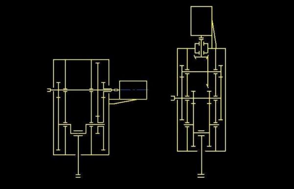
Figure 2.3 – Modernized gate valve drive of a casting ladle.
In the modernized drive, unlike its analogue, the removable electric motor is installed vertically on the gearbox housing and transmits rotation to its high-speed shaft through a bevel gear pair. In addition, the upper end of the connecting rod is connected to an axle rigidly connected to two low-speed wheels offset relative to their centers, which together forms a crank mechanism.
This design solution made it possible to ensure the required compactness of the drive housing in cross section and fit it into the specified dimensions, taking into account the operating conditions of casting ladles with a capacity of up to 10 tons. [3].
Conclusion
- Due to low reliability, the stop-type pouring devices currently used on casting ladles require replacement with modern cassette-type sliding gate valves.
- The introduction of gate systems on casting ladles is hampered for a number of reasons, the main one of which should be recognized as the inconsistency of existing drives with the conditions of filling casting molds with liquid metal.
- The use of a modernized electromechanical drive will make it possible to implement dosed pouring of liquid steel from casting ladles into molds located over a large area.
- To use an electromechanical gate drive on casting ladles with a capacity of 5-10 tons, a coaxial gearbox is proposed, combined with a crank mechanism, in which the function of the crankshaft cheeks is performed by two gear wheels of the last stage. This technical solution made it possible to reduce the transverse size of the gearbox in order to eliminate the extension of its housing beyond the contours of the bucket itself.
At the time of writing this abstract, the master's thesis has not yet been completed. Final completion: June 2024. The full text of the work and materials on the topic can be obtained from the author or his supervisor after the specified date.
References
- Lining of steel-pouring ladles / B.A. Velikin [and others]. – M.: Metallurgy, 1990. – 248 p.
- Pilyushenko V.L., Eronko S.P., Shestopalov V.N. Stopless casting of steel. – K.: Tekhnika, 1991. – 179 p.
- Modernization of the electromechanical drive of a bucket gate valve / S.P. Eronko [and others] // Materials of the 6th International Scientific and Practical Conference “Innovative Prospects of Donbass”. Volume 3. Innovative technologies for the design, manufacture and operation of machines and units. Donetsk, May 26 – 28, 2020 – pp. 33 – 38.
- Kononov V.A. Development of gate systems for casting small ingots and small castings / V.A. Kononov, V.P. Vasilenko, A.A. Alpatov // New refractories. – 2013. – No. 11. – p. 18 – 24.
- Prospects for the use of gate valves during casting / V.A. Kononov [and others] // Steel. – 2002. – No. 3. – P. 59 – 66.
- Zolotukhin V.I. New generation gate systems / V.I. Zolotukhin, N.P. Solomin, S.G. Polubesov // Metallurgy. – 2000. – No. 1. – P. 40 – 42.
- Eronko S.P. Design of rational systems of sliding gates // Metallurg. – 2003. – No. 4. – P. 45 – 47.
- Kulik A.D. The main problems of gate steel casting technology // Steel. – 2001. – No. 2. – P. 13 – 15.
- Finite element method / Ed. Varvaka. – K.: Vishcha School, 1981. – 176 p.
- Ogurtsov A.P. Calculation of the temperature state of a ladle gate valve for various methods of steel casting / A.P. Ogurtsov, I.I. Zhulkovskaya, A.D. Kulik // News of universities. Ferrous metallurgy. – 2001. – No. 4. – P. 11–15.
- Eronko S.P. Calculation and design of equipment for out-of-furnace processing and casting of steel / S.P. Eronko, S.V. Bykovskikh, E.V. Oshovskaya. – K.: Tekhnika, 2007. – 334 p.
- Eronko S.P. Physical modeling of out-of-furnace processing and steel casting processes / S.P. Eronko, S.V. Bykovskikh – K.: Tekhnika, 1998. – 136 p.
- Physical modeling of technical systems of steelmaking: textbook / S.P. Eronko [and others]. – Moscow; Vologda: Infra-Engineering, 2021.– 324 p.
- Innovative metallurgical equipment. Steelmaking: textbook / S.P. Eronko [and others]. – Moscow; Vologda: Infra-Engineering, 2023.– 276 p.
- Eronko S.P., Bykovskikh S.V. Steel casting. Equipment. Technology / S.P. Eronko, S.V. Bykovskikh. – K.: Tekhnika, 2003. – 216 p.
- Seregin V.E. Steel-pouring ladle equipped with a cassette valve with an electromechanical drive // ??Collection of abstracts of the VIII Republican Conference of Young Scientists, Postgraduates and Students. Makeevka April 22, 2022 – P. 6.
- Eronko, S.P. Systems for controlled overflow of liquid steel from the main and intermediate ladles of continuous casting machines / S.P. Eronko, E.S. Tsykhmistro, V.E. Seregin // Materials of the University Scientific and Practical Conference of Young Scientists, Postgraduates and Students in the field of “Engineering”. – Donetsk, 2022. – P. 14 – 18.