
Content
- Introduction
- 1. Review
- 1.1 Goal and tasks of the research
- 1.2 Analysis of the N2 – CH4 system separation problem
- 1.3 Analysis of natural gas purification technologies from nitrogen
- 1.4 Selection of purification technology for a small deposit
- 2. Creating the mathematical model
- 3. Оптимизация параметров технологической схемы
- Conclusions
- List of sources
Introduction
Improved transportation technologies, significant reserves discovered, reduced development costs and environmental sustainability – all this gives reason to believe that natural gas, in particular methane, will remain one of the main sources of energy in the near future. However, there are some factors preventing its widespread use. The increased nitrogen content leads to a decrease in the quality of the gas, a decrease in its energy value, and increases the cost of pumping gas. Therefore, the purification of natural gas from nitrogen is an integral stage of its preparation for use.
1. Review
1.1 Goal and tasks of the research
The relevance of the work is due to the fact that there are currently no relatively inexpensive and effective methods for purifying natural gas from nitrogen, especially for small deposits. Methods of purification from impurities such as water, carbon dioxide (carbon dioxide), hydrogen sulfide (high‐sulfur gas), etc. have been mainly studied. And nitrogen purification seems to be a more difficult process due to the low chemical activity of nitrogen.
The object of research is: the natural gas – nitrogen system.
The subject of the study is: the purification of natural gas from nitrogen in a small field.
The Goal of the research is to study the possibility of reducing the cost and increasing the efficiency of the natural gas purification process from nitrogen using mathematical modeling. To achieve this goal, it is necessary to solve main tasks.
Main tasks of the research are:
- To analyse of existing technologies for natural gas purification from nitrogen.
- To select and verificate of the adequacy of the purification plant model for small deposits.
- To select and optimizate of technological parameters of the process based on the created model.
The proposed tasks will be adjusted based on the results obtained.
1.2 Analysis of the N2 – CH4 system separation problem
Nitrogen is a non‐toxic and non‐flammable gas, does not contribute to corrosion. The presence of nitrogen negatively affects the heat of combustion of a mixture of gases, removes it from the standard range of the Wobbe index and the requirements for the gas product. In addition, the presence of nitrogen affects the cost of pumping the gas mixture and the size of equipment such as compressors and pipelines. According to GOST standards, the final value of the nitrogen concentration after purification should be less than 1%.
Both methane and nitrogen are chemically resistant gases, which is a serious problem for separating them in the N2 – CH4 system. It is also difficult to achieve selective separation of nitrogen from methane due to the almost identical critical diameters of N2 и CH4 (3,64 Å and 3,80 Å respectively) [1].
The complexity of effective N2 – CH4 separation is related to the following factors. Firstly, due to the similar critical diameter between N2 and CH4, it is difficult to develop materials with an accurate pore size for an effective molecular sieve. Secondly, the obligatory presence of intense Brownian motion makes it almost impossible to control the angle at which gas molecules enter the pores of materials. In addition, differences in condensability and polarizability do not contribute to N2 – selective separation. The higher polarizability and critical temperature of CH4 lead to a stronger interaction with most materials, thus preventing the predominant adsorption and penetration of N2 [2].
1.3 Analysis of natural gas purification technologies from nitrogen
Gas separation is a process that can be carried out by fractional condensation (cooling, accompanied by the formation of condensed systems), rectification, sorption with selective absorbents and adsorbents, as well as diffusion through porous partitions (membrane gas separation), etc. Condensation is most widely used in industry in combination with sorption and rectification at low temperatures.
The main available methods of nitrogen removal are cryogenic distillation, absorption, adsorption, membranes and hydrate‐based gas separation [3].
Cryogenic distillation remains the leading technology for large natural gas production plants with a capacity of more than 0.5 million standard cubic meters per day (thousand cubic meters m per day). High gas flow rates make it possible to cover the high capital costs of a cryogenic plant for several years. The method is based on the difference in boiling points of the various components for separation. Four main cryogenic fractionation processes are used to extract nitrogen from natural gas: single‐column, two‐column, three‐column and multi‐column processes. The single‐column process uses a single cryogenic distillation column, which is assisted by an external refrigeration cycle. The absence of an external refrigeration cycle, which is used in LNG plants for source gas with a low nitrogen content, leads to an overspending of commercial gas into produced nitrogen. The other three configurations, which are called multi‐column processes, operate on the basis of a reboiler and a condenser connected by heat. The multi‐column structure is based on the idea of a two‐column process, which was originally invented and widely used to produce pure oxygen [3].
With the membrane method, the separation of gas components is achieved due to differences in the size of molecules and the speed of their movement in the membranes, as well as the mobility of the components of the initial natural gas [4]. Membranes for gas separation are usually divided into three categories, determined by the materials of their manufacture: polymer, inorganic membranes and membranes with a mixed matrix. The transport of gas molecules through the membrane by the dissolution‐diffusion mechanism occurs first due to the absorption of the gas molecule into the membrane, and then due to the diffusion, or penetration, of the molecule through the membrane material.
For adsorption at variable pressure and membrane separation technologies, according to the priority of gas compounds, the separation processes of N2 and CH4 can be sorted into N2 – processes and CH4 – selective processes. In processes selective with respect to CH4, CH4 must be extracted by vacuuming in an adsorption cycle or inevitably concentrated on the permeate side (the flow of matter passing through a semipermeable membrane during membrane separation) at low pressure, which requires additional energy and processes to repeatedly increase the pressure of CH4 to the pressure in the pipeline for subsequent processing, which is significantly increases the cost of the process. Thus, N2 – selective processes are more advantageous for natural gas purification when the characteristics of the adsorbent and membrane reach the standard, and their operating costs are significantly lower than CH4 – selective processes [5]. Organometallic complexes (OMC), zeolites, solid boron, modified materials, etc. are used to separate N2 и CH4 [4, 6].
The latest research is the use of MoS2 as an adsorbent. The result shows that the interaction between any gas and the initial MoS2 is very weak, but the interaction between N2 and MoS2 can be significantly improved by doping B or C [7].
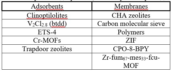
The known membranes and adsorbents used in nitrogen separation are shown on Table 1.
Table 1 – Membranes and adsorbents used in nitrogen separation
Some OMCs in a mixture of nitrogen and natural gas bind nitrogen to a greater extent. Organometallic frameworks are crystalline materials with a large internal surface area and large volumes of pores. The general chemical scheme of reversible nitrogen binding during adsorption by an organometallic complex is shown in Figure 1.

Animation 1 – General chemical scheme of reversible nitrogen binding during adsorption by an organometallic complex,
where R – general organic functionality [5].
(The number of frames is 8, the number of cycles is 5, the volume is 95 KB)
The propensity of methane to hydrate formation makes it possible to separate the components of the mixture by converting methane into a solid phase, in which nitrogen remains in the gas phase. Clathrate hydrates are ice‐like crystalline compounds that consist of cells of water molecules linked by hydrogen bonds that capture small molecules of natural gas inside their cells. Natural gas hydrates are currently an important factor for most operations due to their tendency to agglomerate and block the pipeline or process equipment. For CO2 – N2 – СН4, CO2 gas mixtures, CO2 is the more stable molecule in the hydrate phase, whereas N2 is the least stable. This leads to the preferred occupation of CO2 over CH4 in the hydrate cell or, in the absence of CO2, the preferred occupation of CH4 over N. Most separation processes involve the use of a stirrer reactor and the use of promoter molecules to reduce operating pressure [1].
There is also a way to ensure the complex extraction of valuable impurities from natural helium‐containing hydrocarbon gas with a high nitrogen content with its preliminary deep drying and purification, and further separation from it sequentially (according to boiling points) pentane‐hexane hydrocarbon fraction, butane fraction, propane fraction, ethane, commercial fuel gas, liquid nitrogen and liquid helium of high degrees of purity with the use of effective cryogenic, rectification, absorption technologies, gravity and filtration separation and minimization of energy consumption for the implementation of the process as a whole due to the optimal use of heat recovery during heat exchange between hot and cold streams and the use of turbo expanders, heat pumps. According to the second option, there is a method for producing ammonia, which includes reforming a hydrocarbon with an excess of air to form a stream of initial synthesis gas, removing nitrogen and inert gases from the stream of initial synthesis gas by distillation, while cooling is provided by expanding the liquid through an expander generator, and the upper stream is partially condensed by a discharge stream cooled by expansion liquid residues from the distillation column, and the supply of synthesis gas with a reduced content of nitrogen and inert gases from distillation to the ammonia synthesis circuit, in which the liquid residues are expanded using a liquid expander with the extraction of work [8].
1.4 Selection of purification technology for a small deposit
The main method of interest is a non‐trivial method of absorption by absorption of methane from a mixture of gases with nitrogen, and not vice versa. Nitrogen removal using absorption technologies is not a common practice in the gas industry. There are several commercial N2 removal processes operating through the physical absorption of СН4 in hydrocarbon oil, which have been created to process gas at a feed rate of 2–30 million cubic feet per day. The cost of a large amount of solvent and the recompression of СН4 is prohibitively high for the use of a nitrogen removal unit with selective СН4 absorption in large‐scale LNG plants; therefore, there is a growing need to develop a selective – N2 absorbent N2 [9].
The absorption process is carried out by mineral oils, for example, straight-run naphtha or paraffin oil, essentially consisting of C5–С8, followed by the release of unabsorbed nitrogen. In this case, the molecular properties of N2 and СН4 play an important role, including differences in the kinetic diameter, polarizability, quadrupole and dipole moments of molecules. [10] describes the process of methane absorption by straight‐run naphtha, which includes the following stages:
- Absorption of the hydrocarbon component of natural gas by straight‐run naphtha, essentially consisting of С5–С8 paraffin hydrocarbons, in an absorption device, and the release of unabsorbed nitrogen.
- Desorption of a hydrocarbon component from straight‐run naphtha in a steam column at a temperature at its bottom in the range from 150° to 200°.
- The supply of the desorbed hydrocarbon component to the distribution network.
- Recycling to stage (a) of straight‐run naphtha regenerated during desorption.
Its illustrative scheme is shown in Figure 4.
![Figure 4 – Illustrative scheme of absorption of the hydrocarbon component of natural gas by straight-run naphtha [10]](images/pic_4.jpg)
Figure 4 – Illustrative scheme of absorption of the hydrocarbon component of natural gas by straight‐run naphtha [10]
The main advantage of this method is the availability of mineral oils used as absorbents and the ability to carry out the process over a wide temperature range. The disadvantage of this method is the multi‐stage separation of methane from heavy hydrocarbons, since alkanes are perfectly soluble in each other. The next stage of the study is to find substances and modes in which methane will be absorbed well enough, despite the heavy hydrocarbons in the system, as well as to simulate an absorption plant to select the most suitable conditions and absorbents of the process.
2. Creating a mathematical model
The first step is the correct selection of the initial data, which will allow us to determine the optimal process parameters to achieve maximum efficiency of gas purification and minimize costs.
The main option for purification in small deposits is the concentration of nitrogen in the source gas – from 5 to 15%, based on this, we assume an average initial concentration of 10%. According to GOST, the final concentration value after purification should be up to 1%.
The range of possible changes in the flow rate of the purified gas is from 800 to 2400 cub.m./h, as a starting point we take 800 cub.m./h. Absorption occurs at room temperature and pressure equal to the pressure at the inlet of natural gas. Hence, the temperature at the inlet to the absorber is 200°, and the pressure is taken from [10] – 6 MPa.
The absorption process consists of two main stages:
- Absorption: Natural gas is absorbed by an absorbent (solvent).
- Desorption: Natural gas is released from the absorbent and sent to the distribution network.
Such absorption is carried out either in poppet or in nozzle columns, supplying natural gas from below, and the absorbent from above – for modeling, we use a poppet column. In this case, methane acts as the main component of natural gas, the absorbent is necessary for the composition of С5–С8 paraffin hydrocarbons, therefore, in the system we will calculate the absorption of methane by pentane from the methane–nitrogen system. Nitrogen gas is mainly released from the upper part of the column. An absorbent liquid containing methane is released from the bottom of the column.
The mathematical model describes the dynamics of changes in concentrations in natural gas and absorbent throughout the absorption process. To create a mathematical model, it is necessary to create equations of material balance for each phase of the process (gas and absorbent–liquid). The distribution scheme of the component concentration in the gas and liquid phases of the poppet absorber is shown in Figure 1.
The next step is to select the software. All modeling tools are based on the general principles of calculating the material and thermal balances of chemical industries. DWSIM is an engineering simulator that is an open analog of products such as HYSYS, UniSim and Symmetry. On the basis of DWSIM, it is possible to create digital counterparts of oil and gas industries, engage in complex optimization and significantly increase the efficiency of equipment without capital investments in fixed assets. It is closely integrated with Microsoft Excel. Along with the ability to simulate and optimize complex chemical and technological systems, this software shell allows you to perform design calculations of the parameters of the main technological equipment. With the help of this program, an approximate scheme of the form is created and calculated – Figure 2, similar to the scheme of Figure 1 [10].
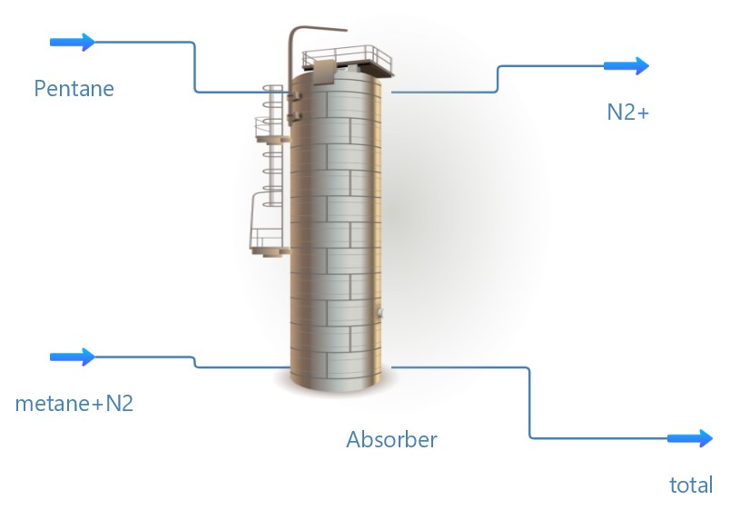
Figure 2 – Scheme of absorption of the hydrocarbon component of natural gas by straight‐run naphtha, created using DWSIM
3. Optimization of the parameters of the technological scheme
To optimize the parameters of the technological scheme, controlled variables are used – variables whose values can be selected within technically acceptable limits at their discretion and thereby influence the course of the technological process. An example of controlled variables can be flow rates, temperatures, pressure in apparatuses, concentrations, etc.
In this case, the process conditions appear to be constant (temperature, pressure, concentration), the main task is to find a suitable absorbent for the process, therefore, in addition to pentane as an absorbent, it is worthwhile to simulate the use of hexane and heptane, and then compare the final results.
Conclusions
Separating nitrogen from methane is a difficult task when using any technology, but without – is impossible to achieve the necessary product quality and increase the efficiency of the equipment. It is necessary to look for new methods and materials for separating nitrogen from methane with high selectivity and efficiency, as well as to improve existing ones. In our opinion, the most promising for relatively small deposits is absorption with the selection of an effective and inexpensive absorbent. The disadvantages of this method seem to be eliminated if it is possible to find a suitable absorbent that would increase the purity of the resulting methane, as well as a simple and effective technology for the regeneration of the absorbent.
This master’s work is not completed yet. Final completion: June 2024. The full text of the work and materials on the topic can be obtained from the author or his head after this date.
References
- Ohs B., Lohaus J., Wessling M. Optimization of membrane based nitrogen removal from natural gas / Journal of Membrane Science, 498, 2016. – p. 291–301.
- Sun Q., Wang M., Li Z., Li P., Wang W., Tan X., Du A. Nitrogen removal from natural gas using solid boron: A first‐principles computational study. Fuel, 109, 2013. – p. 575–581, doi:10.1016/j.fuel.2013.03.032.
- Rufford T. E., Smart S., Watson G. C. Y., Graham B. F., Boxall J., Diniz da Costa J. C., May E. F. The removal of CO2 and N2 from natural gas: A review of conventional and emerging process technologies / Journal of Petroleum Science and Engineering, 94–95, 2012. – p. 123–154.
- The patent № 2559413 C2 Russian Federation, MPK F25J 3/02. Removal of nitrogen from natural gas / H. Bauer, M. Gwinner, D. Garte; No. 2011118883/06: announced 05/11/2011: published 08/10/2015.
- Zhou Y., Yuan Y., Cong S., Liu X., Wang Z. N2 – selective adsorbents and membranes for natural gas purification / Separation and Purification Technology, 300, 2022.
- The patent JPS6342717A Japan. Nitrogen separation / Okamoto H., 1986.
- Shuang W., Huijie L., Mengnan Q., Aijun D., Jianfen F., Qiao S. B/C–doped MoS2 as promising materials for nitrogen removal from natural gas: A first‐principles computational study / Computational Materials Science, 214, 2022.
- The patent RU 2597081 C2 2014153653/05 A method for the complex extraction of valuable impurities from natural helium‐containing hydrocarbon gas with a high nitrogen content Mnushkin I./ 2016.09.10. Application № 2014153653/05, 2014.12.29.
- Jusoh N., Lau K. K., Shariff A. M., Yeong Y. F. Capture of bulk CO2 from methane with the presence of heavy hydrocarbon using membrane process. International Journal of Greenhouse Gas Control, 2014, 22, 213–222.
- The patent № 2185226 C2 Russian Federation, MPK B01D 53/14, C10L 3/10. A method for removing nitrogen from natural gas / L. Chicarelli. – No. 2000103939/12 EDN MPXDXN; application 02/18/2000: published 07/20/2002.