Abstract
Content
- Introduction
- 1. Relevance of the topic
- 2. Purpose, functions and tasks of the ACS
- 3. General characteristics of the cleaning process and its analysis
- 3.1 Analysis of the technological process as a control object
- 3.2 Mathematical model of SPGs
- 3.3 Synthesis of ACS by a synthesis gas purification absorber
- Conclusion
- List of sources
Introduction
Modern industry cannot do without the automation of production processes. The automation of production processes is an important trend in contemporary industry as a whole. It allows for increased production efficiency, reduced manufacturing costs, minimized waste, and improved product quality. Various technologies are used for this, such as automated control and process management systems, robotics, and others. As a result, production becomes more efficient, economical, and safe for both workers and the environment. If a process is not automated, it may lead to errors, production delays, and a decline in product quality. Therefore, the automation of production processes is a necessary condition for the successful operation of modern industrial enterprises.
Monoethanolamine (MEA) scrubbing is a technology used for the removal of hydrogen sulfide (H2S) and carbon dioxide (CO2) from syngas. Syngas, which is produced from natural gas, coal, or biomass, contains significant amounts of hydrogen sulfide and carbon dioxide, both of which are harmful to the environment and can negatively affect the operation of various devices and equipment. This technology is based on the use of a monoethanolamine (MEA) solution, which absorbs hydrogen sulfide and carbon dioxide from the syngas. After the syngas is purified, it undergoes further processing to produce hydrogen, which can be used in various industrial processes such as ammonia, methanol, and other chemical production. The advantages of MEA scrubbing include high efficiency in absorbing CO2 and H2S, low equipment costs, the ability to recycle the MEA solution in the cycle, as well as the capability to process the gas mixture at high temperatures and pressures. This technology is one of the most widely used methods for syngas purification and is commonly applied in the industry.
1. Relevance of the topic
Modern technological processes and technical systems cannot function effectively without automation and control systems. The application of automation systems allows for minimal errors in management and helps achieve optimal operational parameters for the entire process. The characteristics of the final product are formed during technological processes, and imperfections in these processes, as well as wear and aging of equipment, can lead to deviations from nominal values, reducing the quality, efficiency, and safety of the product. All technological parameters that affect product quality must be continuously monitored, and the management of the technological process and production as a whole must minimize the impact of destabilizing factors. The effectiveness of process control and its automation are crucial criteria that determine the quality of the final product, including the ammonia production process considered in this work [8].
2. Purpose, functions and tasks of the ACS
The goal of the developed system is to improve the efficiency of the monoethanolamine (MEA) syngas scrubbing process through the design of an automatic control system for the absorber, which will enhance the effectiveness of the process while reducing resource consumption.
The developed automatic control system for the ammonia synthesis column should perform the following functions:
1) Control functions:
– Control of pressure in the absorber;
– Control of the saturated absorbent level in the absorber;
2) Protection functions:
– Overload protection;
3) Informational functions:
– Collection of information about the condition of the absorber from sensor signals and transmission to the control device;
– Alarm signaling in case of emergency situations.
3. General characteristics of the cleaning process and its analysis
The gas is purified from CO2 at a pressure range of 15 to 25 kg/c2. The desorption process of the monoethanolamine solution occurs at a pressure of 2.5 kg/cm2. Typically, a 15% aqueous solution of monoethanolamine is used (2.5 moles of MEA per 1 liter of solution).
Figure 1.1 shows the schematic diagram of a plant for natural gas purification from CO2 and H2S using absorption [2,3,9] with a monoethanolamine solution.
In the monoethanolamine (MEA) scrubbing process, in addition to CO2, other harmful impurities, such as hydrogen sulfide (H2S), are also removed from the gas. The purification process is carried out as follows. Natural gas, at a pressure of 15-25 atm, enters the absorber 1, where it flows upward through a Raschig ring packing, which is irrigated with a 15% solution of monoethanolamine. The purified gas then passes through separator 2, where MEA solution droplets are captured and is further directed to the liquefaction unit. The solution flows from the separator into the absorber's collection system. The solution from the absorber's collection system is continuously fed for regeneration into the desorber 4, where it is preheated in heat exchanger 3 to 115°C. In the desorber 4, the solution flows downward over the packing, gradually regenerates, and the released carbon dioxide (CO2), along with water vapor, rises upward and exits the device. The water vapor is generated in the heater 5, which is heated by steam at a pressure of 4-5 atm.[5].
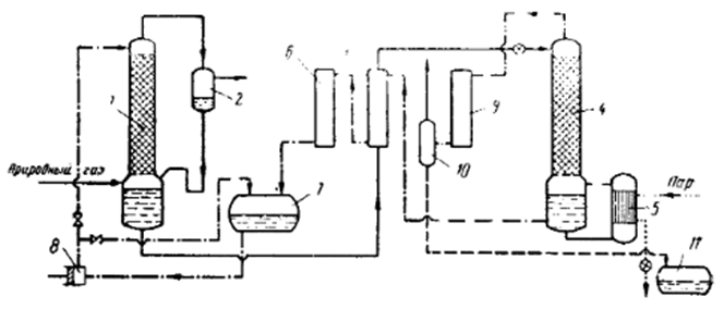
Figure 1.1 – Schematic diagram of a plant for natural gas purification from CO2 and H2S using absorption with a monoethanolamine solution.
1 – Absorber, 2 – Separator, 3 – Heat exchanger, 4 – Desorber, 5 – Heater, 6 – Cooling unit, 7 – Liquid collection tank, 8 – Pump, 9 – Condenser, 10 – Gas separator, 11 – Drainage collection tank.
The regenerated solution from the desorber collection tank is directed to heat exchanger 3, where it is cooled from 135°C to 50°C, and then to the cooler 6, where it is further cooled to 30°C before being sent to the collection tank 7. Pump 8 transfers the solution from the collection tank to the upper part of the absorber column 1. To regulate the amount of solution fed into the absorber, a bypass line is provided, allowing part of the solution to be returned to the collection tank.
Carbon dioxide (CO2), along with water vapor and a small amount of monoethanolamine vapor, exits from the top of the desorption column 4 and enters the condenser 9, which is cooled by water. The condensed water vapor is separated from CO2 in the gas separator 10, the water flows into the drainage collection tank 11, while the carbon dioxide is released into the atmosphere.
3.1 Analysis of the technological process as a control object
Based on the analysis above, the main controlled variables for the syngas purification absorber are: pressure in the absorber Рв; iquid level in the absorber hж.
The manipulated variables are: flow rate of purified gas Fог, flow rate of saturated absorbent Fна.
Disturbance variables are: flow rate of the incoming gas mixture Fис, concentration of the absorbed absorbent Cис.
Thus, the material flow diagram and information variables are obtained (Figure 1.2), as well as the control object representation diagram for the gas purification absorber (Figure 1.3).
The main input material flows are: the incoming gas mixture (characterized by the variable Fис), and the saturated absorbent (characterized by the variable Fна).
The main output flows are: the purified gas (characterized by the variable Fог) and the saturated absorbent (characterized by the variable Cис).
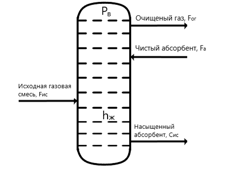
Figure 1.2 – Material flow diagram of the syngas purification process.
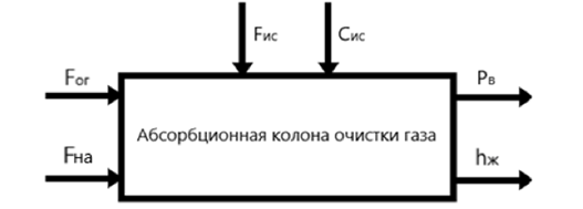
Figure 1.3 – Absorption column for gas purification as a control object.
Mathematical model of SPGs
The structural diagram of the Automated Control System (ACS) for the pressure in the syngas purification absorber is developed based on the chosen control concept for this object. In developing the control concept for this work, it was decided to ensure the accuracy and cost-effectiveness of pressure regulation in the syngas purification absorber by using a combined control strategy.
The structural diagram of the Automated Control System (ACS) is shown in Figure 1.4. The structure of the ACS [10] corresponds to the combined control strategy and includes the main feedback loop for the primary controlled variable – pressure in the absorber, as well as a compensatory channel for the main disturbance – the flow rate of the incoming gas mixture.
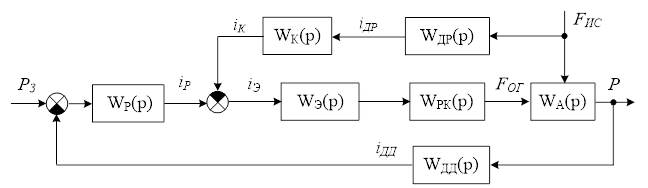
Figure 1.4 – Structural diagram of the combined ACS for the absorber.
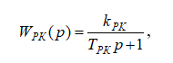
The structural diagram includes the following notations: WР(р) – transfer function (TF) of the pressure regulator, WК(р) – transfer function (TF) of the compensator for the flow of the incoming gas mixture, WЭ(р) – transfer function (TF) of the electric drive of the regulating valve for purified gas, WРК(р) – transfer function (TF) of the regulating valve for purified gas, WДД(р) – transfer function (TF) of the pressure sensor, WДР(р) – transfer function (TF) of the flow sensor for the incoming gas mixture, WА(р) – transfer function (TF) of the control object – the syngas purification absorber.
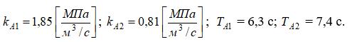
The analysis of the literature sources [1,6,7] showed that the change in the controlled variable – pressure in the absorber – in response to the specified manipulated variable (purified gas flow) and disturbance variable (incoming gas mixture flow) is smooth, non-oscillatory, and aperiodic. Therefore, the mathematical model of the control object – the syngas purification absorber – can be represented in the form of the following transfer functions:
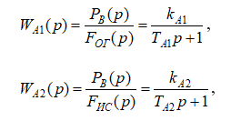
where
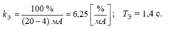
The actuator – the electric drive of the purified gas regulating valve WЭ(р) receives a direct current control signal iЭ = 4…20 мА. ПThe electric drive can be described as a first-order aperiodic element with the following transfer function:
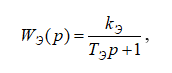
where
The obtained model of the electric drive for the regulating valve (3.3) needs to be supplemented with a nonlinear element that accounts for the limitations on the maximum and minimum displacement of the output shaft of the actuator, which ranges from 0% to 100%.
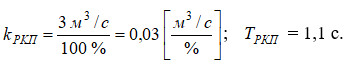
The model of the purified gas regulating valve WРК(р) links the displacement of the actuator shaft with the flow rate of purified gas and can be described as a first-order aperiodic element with the following transfer function:
where
Thus, the structural diagram of the syngas purification absorber model has been obtained, as shown in Figure 3.2.
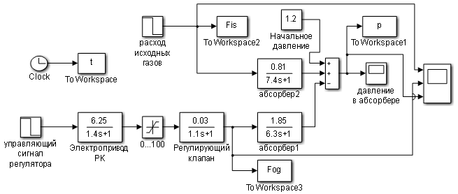
Figure 1.5 – Model diagram of the control object – syngas purification absorber.
3.3 Synthesis of ACS by a synthesis gas purification absorber
Figure 1.6 shows the model diagram of the ACS for pressure control in the syngas purification absorber, with a compensatory channel for the main disturbance – the flow rate of the incoming gas mixture (lower part of the diagram) and without the compensatory channel (upper part of the diagram).
The pressure regulator parameters (Figure 1.6) were tuned using the automatic tuning function of the PID control block from the Simulink simulation package, which allows the developer to specify the desired settling time and the sensitivity of the regulator (Figure 1.7).
As a result of the automatic tuning and using the quality indicators specified at the beginning of this section, the following values for the pressure PI-controller parameters were obtained: kП = -0, 361; kИ = -0, 065. As a result of the calculations, the following value for the compensator of the main disturbance – the flow rate of the incoming gas mixture – was obtained kК = -0, 746.
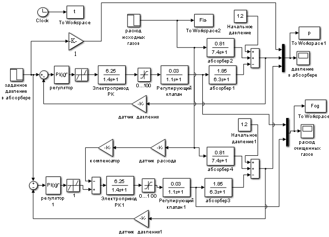
Figure 1.6 – Simulation diagram of the ACS for pressure control in the syngas purification absorber.
To assess the effectiveness of the theoretical synthesis of the ACS for pressure control in the syngas purification absorber – including the selection and tuning of the PI pressure regulator and the compensator parameters for the main disturbance (the flow rate of the incoming gas mixture) – a simulation of the combined ACS for pressure control in the syngas purification absorber was carried out. This simulation considered stepwise changes in the disturbance variable – the flow rate of the incoming gas mixture, and the results are presented in Figures 1.7 to 1.9. Additionally, the simulation was performed for linear changes in the main disturbance – the flow rate of the incoming gas mixture, and the results are shown in Figures 2 to 2.2.
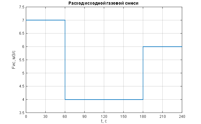
Figure 1.7 – Stepwise change in the main disturbance – flow rate of the incoming gas mixture.
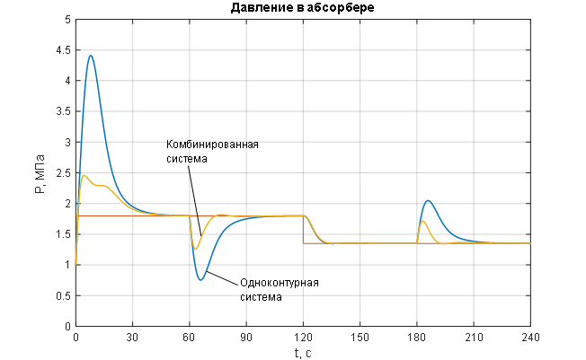
Figure 1.8 – Transient characteristics of the ACS for the controlled variable – pressure in the syngas purification absorber.
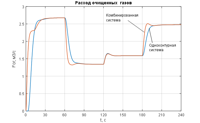
Figure 1.9 – Change in the manipulated variable of the ACS – flow rate of purified gas.
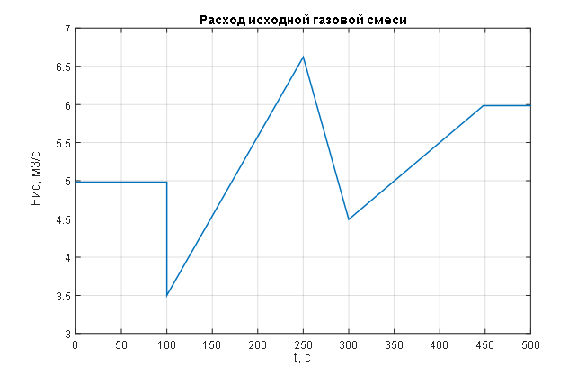
Figure 2 – Linear change in the main disturbance – flow rate of the incoming gas mixture.
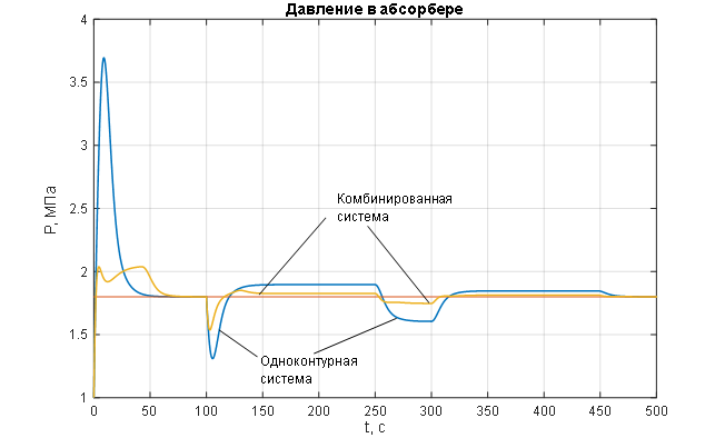
Figure 2.1 – Transient characteristics of the ACS for the controlled variable – pressure in the syngas purification absorber.
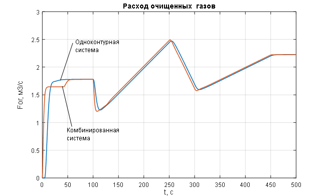
Figure 2.2 – Change in the manipulated variable of the ACS – flow rate of purified gas.
The analysis of the transient characteristics for the controlled variable – pressure in the syngas purification absorber (Figures 1.8 and 2.1) – allows us to conclude that the pressure control in the absorber is of satisfactory quality when processing disturbances of any kind (Figures 1.8 and 2.1) using a combined ACS structure with a compensator for the main disturbance – the flow rate of the incoming gas mixture: the pressure maintenance process is monotonic with no steady-state error and necessary dynamics, the settling time of the transient process is 12 seconds (with a required maximum of 15 seconds); the disturbance rejection time is 14 seconds (with a required maximum of 20 seconds); the deviation of the controlled variable under the influence of disturbances does not exceed the allowable 25%. In contrast, the single-loop ACS without a disturbance compensator (Figures 1.8 and 2.1) shows unacceptable deviation of the controlled variable under the influence of disturbances and unsatisfactory dynamics, with the disturbance rejection time being 35 seconds (with a required maximum of 20 seconds). The analysis of the curves for the change in the manipulated variable of the ACS – the flow rate of purified gas (Figures 1.9 and 2.2) – leads to the conclusion that its variation occurs within technologically acceptable limits: FОГ = 0…2,7 м3/с with an allowable range of FОГдоп = 0…3 м3/с.
Conclusion
The development of the automatic control system (ACS) for the monoethanolamine (MEA) syngas purification process was carried out. An overview of the features of the MEA syngas purification process was conducted. The absorber was analyzed as an object of control and regulation, and the object of control was formalized. Material flow diagrams and information variables were developed, and a set of controlled variables, manipulated variables, and disturbances was defined. A concept for creating the automatic control system was proposed. Using this concept, a structural diagram of the ACS was created, and a mathematical description of its main components was developed. The selected set of technical means for the ACS and the developed regulation algorithms enable the full implementation of the necessary control and regulation functions in the process of syngas purification using monoethanolamine in the absorber.
List of sources
- Дытнерский, Ю.И. Процессы и аппараты химической технологии / Ю.И. Дытнерский. Часть 2. – М., «Химия» 2002. – 368 с. [Ссылка]
- Рамм, В.М. Абсорбция газов / В.М. Рамм. – М.: Химия, 1976. – 656 с. [Ссылка]
- Касаткин А.Г., Основные процессы и аппараты химической технологии / А.Г. Касаткин. – М.: Изд-во АльянС, 2005. – 753 с. [Ссылка]
- Иванова Г.В. Автоматизация технологических процессов основных химических производств: Методическое пособие. Часть 2 / СПбГТИ(ТУ).-СПб. – 2003.- 70с. [Ссылка]
- Герш С.Я. Глубокое охлаждение. Ч.2: Конструкции машин и аппаратов, тепловые расчеты, описание установок глубокого охлаждения. – 1960 – 485 с. [Ссылка]
- Мельников Е.Я. (ред.) Справочник азотчика. Том 1. – 1967. – 492 с. [Ссылка]
- Мельников Е.Я. Справочник азотчика. Издание 2-е. – 1987. – 464 с. [Ссылка]
- Егоров А. Ф. Интегрированные автоматизированные системы управления химическими производствами и предприятиями : учебное пособие для вузов / А. Ф. Егоров. — Москва : Издательство Юрайт. – 2024. — 248 с. [Ссылка]
- Шувалов В.В., Огаджанов Г.А., Голубятников В.А. Автоматизация производственных процессов в химической промышленности: Учебник. — 3-е изд., перераб. и доп. — М.: Химия. – 1991. — 480 с. [Ссылка]
- Божко В.И. Системы управления химико-технологическими процессами. Часть 2. – 2020. [Ссылка]