Personal web-site of DonNTU master   Timonin Yuriy
You can find:

Master thesis
"Control system for parallel minipulator with six degrees of freedom "

Scientific supervisor:
prof. Horhordin Aleksandr Vladimirovich
Animated parallel manipulator
Contents:
1. General facts
2. The review of existing mechanisms with parallel kinematic links
3. Mathematical model of the parallel manipulator with 6 degrees of freedom
4. Simulating of the parallel manipulator
5. References


1. General facts   up

        The idea of the mechanism with parallel kinematic links (parallel manipulator) was offered and realized by Gough and Stewart in 50 - 60 of the XX century. This mechanism was called Stewart-Gough platform. Stewart-Gough platform is basically used for flying simulation. Then Hunt in 1983 carried out systematic study of the kinematic structure of parallel manipulators. Since then parallel manipulators have been studied very extensively. The parallel manipulators have advantages of higher stiffness, higher load capacity, and lower inertia to serial manipulators.
        Usually, the parallel manipulator consists of a moving platform which is attached to the fixed platform – called “base” by several links (legs). Basically the number of legs is equal to the number of degrees of freedom. Each link is actuated with a drive and all drives can be placed on or nearby base. Due to the fact that external load at the mobile platform are divided among the drives, parallel manipulators have good load capacity.

2. The review of existing mechanisms with parallel kinematic links   up

        The task of my master thesis is detailed studying and analysis of the parallel manipulators with six degrees of freedom and designing control system for one of the manipulator. The control system must be designed for Hexaslim type parallel manipulator. Therefore the review of the basic types of parallel manipulators with six degrees of freedom and control strategies for them is performed here.
        All robots can be classified to various criteria, such as their degrees of freedom, kinematic structure, drive technologies, workspace geometry and motion characteristics. Classification to kinematic structure is considered to be one of the main. According to this classification robots are divided into three groups: serial, parallel and hybrid manipulators. A robot is said to be a serial manipulator if its kinematic structure is an open-loop chain, a parallel manipulator if it has closed-loop chains, and hybrid manipulator if it consists of both closed- and open loop chains.
        The topology of kinematic links of parallel manipulators is accustomed to describe with series of the letters coding the type and sequence of kinematic pairs. The letters R, P, U, and S are used to denote respectively revolute, prismatic, universal, and spherical joints. When a joint is actuated, its corresponding letter is underlined. Thus, the chain of letters (one of which is underlined) designating the joints in a leg, ordered consecutively from the base to the mobile platform, is used to denote the leg.
        In the area of parallel mechanisms with six degrees of freedom, the most popular one is 6-UPS parallel manipulator called Stewart-Gough platform. Indeed, almost all existing parallel mechanisms with six degrees freedom used in the industry, flying simulations or entertainment are based on 6-UPS architecture. Stewart-Gough platform is no doubt an excellent choice for these applications, as it is the stiffest of all 6-DOF architectures (only axial loads in the legs) and allows the use of powerful (yet expensive and messy) hydraulic actuators. The example of Stewart-Gough platform is shown in the figure:

Stewart-Gough platform

        The second most popular 6-DOF architecture is undoubtedly the 6-RUS one. Often the U joints in the legs are replaced by S joints. This leads to a redundant DOF in each distal link which, however, does not change the properties of 6-RUS parallel mechanisms. Similarly, the U and S joints in each leg may be interchanged without any change in the mechanism characteristics. Therefore, in what follows, we will make no difference between legs of type RUS, RSS or RSU, and refer to them simply as RUS.
        The main advantage of 6-RUS parallel mechanisms is first of all their light mobile part, as the heavy motors are mounted on the base. The second advantage is the possibility for use of cheap electric motors. Certainly, the ability to use thin rods for the distal links and thus reduce the risk for link interference is beneficial too. The main disadvantage of such manipulators is their highly complicated kinematic analysis.
        One more widespread type of parallel manipulator is 6-PUS mechanism. You can see an example of such mechanism in an animated picture in the beginning of this page. In comparison with Stewart-Gough platform the weight of mobile parts of the 6-PUS mechanism is less. Due to using linear drives the HEXAPOD-robot with topology 6-PUS has higher static (especially mechanical stiffness) and dynamic (especially acceleration) characteristics.
        There are quite a few control strategies for controlling parallel manipulators. The first is the PID gain updating algorithm by a simple adaptive law. Next, a model reference adaptive algorithm can be applied to compensate the errors of system parameters and to obtain robustness against external disturbances. Some researchers investigated an inverse dynamics control law in which parameters in a simplified inverse dynamics model of a HexaSlide type parallel robot are updated. Lee and Kim proposed a model-based joint-axis sliding mode controller. In some cases robust systems can be applied.

3. Mathematical model of the parallel manipulator with 6 degrees of freedom   up

        To obtain mathematical model of the parallel manipulator we need to solve kinematic and dynamic equations. To solve inverse kinematic problem is to find all possible sets of actuated joint variables and their corresponding time derivates which will bring the end effector to the set of the desired position and orientations. On the other hand, sometimes it’s known the set of the desired position and orientations of the end effector, and sets of actuated joint variables and their corresponding time derivates must be found. This is called the direct kinematic problem. Statics deals with relations of forces that produce equilibrium among the various members of a robot manipulator. Dynamics deals with the forces and/or torques which are needed to cause the motion of manipulator. Like kinematics, there are direct and inverse dynamics.
        For the solving inverse kinematic problem two Cartesian coordinate systems, frames A(x,y,z) and В(x,y,z), are fixed to the base and mobile platform, respectively. The transformation from the mobbing platform to the fixed base can be described by the position vector p of the centroid P and the rotation matrix of the moving platform.

Mathematical model

        Let u,v and w be three unit vectors defined along the u ,v and w axes of the moving coordinate system. The rotation matrix can be written as:

        The length of the i-th limb is obtained by taking the dot product of the vector with itself:

        This equation written six times, once for each i = 1,2,…6, yields six equations describing the position of the moving platform with respect to the fixed base. To solve the inverse kinematic problem we need to take the square root of foregoing equation.

        Hence, there are generally two possible positions for the each limb, but the negative limb length is physically not feasible.

4. Simulating of the parallel manipulator   up

        The task of the controlling of the parallel manipulator is to find a method to actuate the six leg forces to properly position the mobile platform given a desired trajectory. For this problem, we are given a desired position and orientation of the mobile platform with respect to the fixed base plate. These desired values might change over time. For the platform’s model the six leg forces are the inputs into the plant while the outputs are the lengths and velocities of the six legs.
        Traditional method for designing the controller for parallel manipulators requires manipulating difficult equations that modeled the physical components. Then, these equations have to be solved using complex numerical integration techniques. This can be avoided using special tools such as dynamic simulation software. To simulate mechanical parts it’s possible to use MATLAB/SimMechanics, and for simulating a regulator - Simulink.
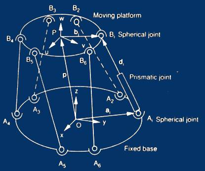
       In the first the plant model is built using SimMechanics. The mechanical components of the manipulator compose of a top plate, a bottom plate, and six legs connecting the top plate to the bottom plate. Each leg contains two bodies connected together with a cylindrical joint. The upper body connects to the top mobile plate using a universal joint, and the lower body connects to the base plate using a second universal joint.
        For imitation of the base the SimMechanics ground block is used. This block connects to the universal joint block. Connecting universal joint block to a body block we get the lower leg. Next, we add another body block to represent the upper leg. Then we use a cylindrical joint block to connect the lower leg to the upper leg. To move the legs, we use a joint actuator block from the Sensor & Actuators Library in SimMechanics. This joint actuator is used to control the translational degree of freedom of the cylindrical joint. With help of the joint sensor block we are able to measure the position and velocity. All elements of the model of a leg are united into one block, i.e. the subsystem is formed. Now it is possible to build mechanical model of the parallel manipulator in SimMechanics.

Mechanical model

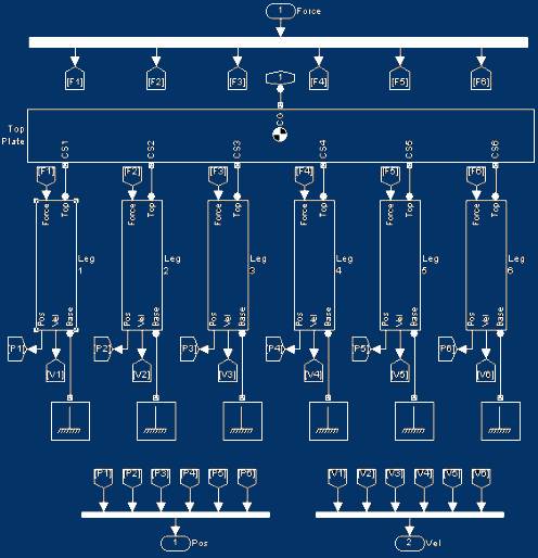
        The control signal formed by a regulator, moves on demultiplexer which has six outputs. Signals from these outputs are input signals for joint actuator block of each leg. All six legs affect a mobile platform - block top plate. The each leg subsystem has two outputs signals: position and speed which are used as feedback for a regulator. Thus, we get the model of the parallel manipulator.
      The basic goal of the controller is to specify the desired trajectory of the top plate in both position and orientation. This desired trajectory then is mapped to the corresponding trajectory in the legs using inverse kinematics. Finally, the controller forms master control for each leg to command the leg to follow the desired trajectory.
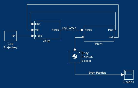
        As a low level regulator the PID regulator is used. Its inputs are the current position, speed and desirable position of legs. Finally, the model of a control system and control object is put together. This system is represented in the following figure:

Entire model

        The parallel manipulators have advantages of higher stiffness, higher load capacity, and lower inertia to serial manipulators. The disadvantages of parallel manipulators are next: limited and rather small workspace and very complex mathematical description.
        During the functioning of the parallel manipulator so-called «special positions» may take place. In such positions the links of the manipulator can intersect. This leads to the breakage of the device. Therefore, the control system of the manipulator should not only provide speed and overcorrection requirements, but also to avoid special positions.
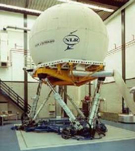
        There are various applications of the parallel manipulators such as flight simulator, handle vehicle maintenance positioning of satellite communication dishes and telescopes. Its can be used both in industry applications and for entertainment. It does without saying that studying of the parallel manipulators will be developed in future.


References   up
1.

Lung-Wen Tsai. Robot Analysis: The mechanics of serial and parallel manipulators.– New York: John Wiley&Sons Inc., 1999. – 505С.

2.

"Geometric Analysis of Parallel Mechanisms"; Ilian Bonev.
Internet-resource .

3.

"Robust Adaptive Control of a Hexaglide Type Parallel Manipulator"; John Phil Kim, Sung-Gaun Kim, Jeha Ryu.
Internet-resource .

4.

Скляренко Е.Г. "Оптимизация конструкции механизма с параллельными кинематическими связями и шестью степенями свободы."

5.

"Simulink 4. Специальный справочник" В.Дьяконов- Санкт-Петербург, 2002. – 517С.

6.

http://www.parallemic.org

7.

http://www.mathworks.com


up main page masters portal

Please, choose the language:
Русский
Українська
English


rus | ukr | engl
Emblem of CITA

DEPARTMENT   OF   COMPUTER   INFORMATION

DEPARTMENT   OF   COMPUTER   INFORMATION

DEPARTMENT   OF   COMPUTER   INFORMATION

TECHNOLOGIES   AND   AUTOMATION

TECHNOLOGIES   AND   AUTOMATION

TECHNOLOGIES   AND   AUTOMATION