There are 7 extruders at the plant, each being driven by an electric motor through a gearbox with 5 shafts, including the two screw shafts in the extruder itself (Fig. 1 shows the complex arrangement of gears). The extruders are not monitored by the permanent monitoring system, but are covered by the periodic measurement and analysis programme.
The manufacturer of the extruders recommends that the extruders be stripped after 25000 running hours for repair of the gear wheels and rolling element bearings. However, since the introduction of vibration monitoring using spectrum comparison, the condition of the extruder gears and bearings could be followed closely and the maximum possible life obtained. This has allowed a rationalization of the maintenance interval, which has in some cases been doubled to 50000 hours, and is likely to be increased further as more experience with the vibration signatures from these machines is collected.
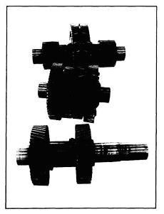
Fig 1 – The extruder gears
Needle Bearing Damage
It appears that extruders which have minor damage to the small needle bearings carrying the screws (faults which are normally very difficult to detect), exhibit an increase in the very low frequency range, see Fig. 2. These frequency components are lower than the shaft running speeds, and are dominated by sub-harmonics of the rotational speed of the screws and the output shaft from the gearbox, that is V2, and V3 etc. of these shaft speeds. This is an effect often encountered in connection with looseness in a machine, suggesting that the needle bearing damage is associated with excessive looseness of the screw shaft.
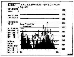
Fig 2 – Spectrum from the extruder showing increases at the very low frequencies
Gear Teeth Damage
Gear faults such as misalignement, unevenness and local tooth damage are normally reflected as sidebands around the toothmesh frequency. The frequency spacing of these sidebands is equal to the shaft speed. Fig. 3 shows a zoomed spectrum from the extruder gearbox, centered around the toothmesh frequency at 696,25 Hz. The sideband spacing of 11,3 Hz, which is clearly visible, is equal to the intermediate shaft speed. When the gearbox was stripped for maintenance, the gear wheel on the adjoining shaft was seen to have small local damage on part of the tooth circumference.
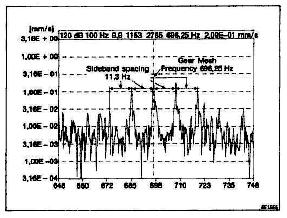
Fig 3 – Zoomed narrowband spectrum from the extruder gearbox, clearly showing the sidebands around the toothmesh frequency
The vibration measurements on these machines have until now been made off-line. However, in view of the encouraging results with the off-line monitoring, it is now being considered to extend the on-line permanent monitoring system to cover these extruders as well.
Conclusions
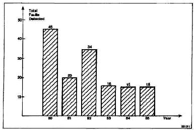
Fig 4 – Number of faults detected using vibration monitoring since the plant began full operation in 1980
The system has shown itself to be capable of detecting both quickly and slowly developing faults. It not only provides the security of knowing that sudden deterioration of machine condition will be detected in time for action to be taken, but also allows accurate detection and diagnosis of the faults to be made, well in advance of breakdown. In many cases, early indication of a worsening of condition has been given. The machine condition could then be followed very closely to continue operation for the longest possible time and to determine the best time for maintenance.
Some of the advantages of the system are outlined below:
Permanent Monitoring
Permanent monitoring gives the safety of knowing that there is a continuous watch on machine condition.
Broadband Monitoring
Permanent broadband monitoring gives warnings of sudden deterioration of machine condition, thus avoiding serious breakdown.
Spectrum Comparison
Spectrum comparison gives early detection of changes, allowing minor changes in condition to be detected and the reason for the fault to be diagnosed. Trend Analysis then allows these changes to be followed closely, and the machine run for maximum possible time.
Computer Based Systems
Computer based systems offer the advantage of automatic control of the monitoring system, giving ease of data handling and large data storage.
Fig. 4 shows the number of faults that have been detected using the vibration monitoring programme. It is interesting to see that the curve appears to follow the beginning of the "bath tub" failure curve - the number of faults was high at the very beginning when machinery was new and prone to teething problems, and then dropped off to a steady rate.
It is, of course, not possible to say that each and every fault detected by the monitoring system would have caused an unexpected breakdown. However, the cost of just one agitator breakdown would pay for the complete monitoring system. In the original proposal for the monitoring system, the maintenance management at Statoil expected a pay-back time of 18 months. The actual pay-back, at a very conservative estimate, was in fact well inside this time.