 |
Dorofeyev ViktorFACULTY: ELECTROTECHNICALSpeciality: Electromechanics systems of automation and electrical driveTheme of master's work: "Synthesis diagnostics apparatus of controlled rectifier"Leader of work: Valeriy Matveevich Shymyatskiy |
ABSTRACT |
SYNTHESIS OF LOGICAL SWITCHING DEVICESometimes rotating direction needs a change when electric drive works. For this reversing method exist. From one-sided conduction of thyristors reversing thyristor rectifier can be obtained using two sets of irreversing thyristor rectifiers. At that each of the groups will define only one direction.The control of reversing thyristor rectifiers can be realized in two way: 1. joint 2. separate The separate control consist in control pulses feed on one thyristor group, at the same time second group is closed. It is completely exclude passing of equating current. It should be noted that a new element LSD (logical switching device) is appearing in the circuit. Logical switching device makes such functions: 1. The choice of group for work depending of sign control voltage it is the difference of assigning voltage and feedback voltage. 2. Exclusion of opening standing group in the presence of a current in working group and taking down control pulses from the working group when current flows through it. There are circuits of LSD in which used: 1. two conductivity sensors 2. one conductivity sensor The circuit with one conductivity sensor is used.
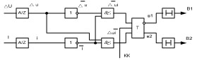
â1 (t + 1) =f[i, ΔU, â1t ] â2 (t + 1) =f[i, ΔU, â2t ] b1, b2 is control signals of blocking first and second thyristor groups. May be 0 or 1. Zero is absence of blocking. One is blocking. â1 (t + 1), â2 (t + 1) is control signals of blocking first and second thyristor groups for the next moment of time. Synthesis of LSD can be made: Plotting the diagrams of changing input signals when reversing is made or during the increase of speed with recuperation. On the diagram (figure 1) analog quantities are marked with capital letters and digital quantities are marked with small letters. â1(t+1) =Δu i â1t + Δu i â1t + Δu i â1t + Δu i â1t On the figure 1 in this table suitable points on the state diagram are located in columns and the state of suitable parameters is located in lines on. Â1(t+1) = [(ΔU + ΔU) i +ΔU i ] Â1t + ΔU i Â1t = ( ΔUi + ΔUi +ΔUi + ΔUi ) Â1t _ _
_ _
_ _ _
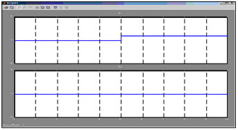
Results of the work of modeled circuits of LSD are represented on the oscillogram (figure 4). This results show that modeled circuit of LSD replies to the technological requirements which are set to the control system of reversing of thyristor rectifier.
|


| Curriculum Vitae | Library | Individual work |
| Report about the search | Abstract | Links |