 |
|
[DonNTU] |
|
[Master's portal] |
|
 |
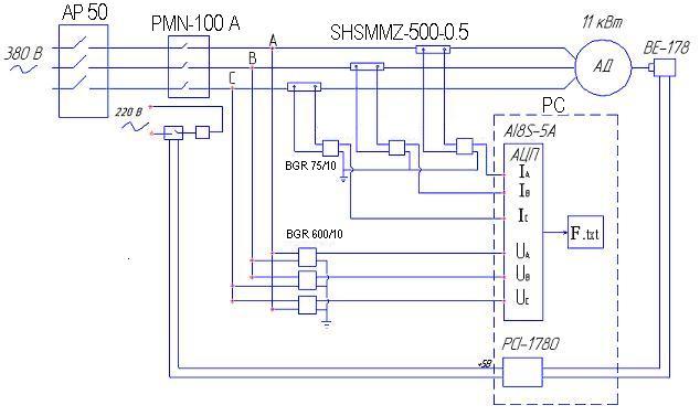
AbstractMaster's work theme: «Working out and investigation of numerical system of parameters control of asynchronous motors»Master's work chief: c.t.s., doc. Garmash V.S.Urgency of themeAt present time motors of alternating current are the first-rate consumers of electric power. They use over 80 % electric power of the country. Many efforts of motor’s damages allow to have the statistics: damages of stator’s elements – 38%; damages of rotor’s elements – 10%; damages of bearing’s elements – 40%; other damages – 12%. Exploitation of motors results in financial losses when they are be found in inadequate state. Consequently diagnostics of asynchronous motors is necessary. Current state problemToday the method of vibration of the state of electric motors are widely used. This method is quite expensive and time-consuming, because it requires special measuring equipment, is not always possible to rebuild because of the vibrations, etc. The essence of «state technology» is that maintenance and repairs are made depending on the actual current technical conditions of machinery. In doing so, the cost of maintenance of electric motors is reduced by 50-75%. It is known that most often the rotor and the stator windings damages of AD, which are suggested to diagnose a number of methods. The disadvantages of these methods may include the following: error in the presence of pulsations diagnosis and harmonic components, the voltage supply, as well as the difficulties in assessing the technical condition of the electric motor, using one of the criteria. The purpose of workThe aim is to develop hardware and software of digital control system features of an asynchronous motor. Using this hardware to receive digital data that can be used in a number of methods for diagnosis of electric motors. The according to data parameters we can assess operational status of an electric motor, accurately define its parameters, to explore the engine in different modes. The structure of the complex and the measurementsThe complex includes a personal computer, analog-digital converter (ADC) with the necessary software for the collection and storage of information interchange photon-coupled firm L-Kard, magnetic actuators, speed sensor, as well as a set of programs for processing the information received. The diagram complex is represented in Figure 1.
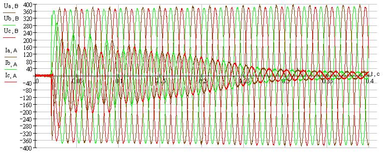
Figure 1 - The diagram complex The scheme is connected via AP-50 automatic protection to the AC 380 V. From three phases are connected to the magnetic actuators PMN-100, by which further commutation is produced. For starters through the shunt 75 SHSMMZ-500-0.5 asynchronous motor MA-143-1 / 4 (Rn = 11 kW, U n = 380 V) is connected object, with sensor angular movements of VE-1780 is connected the shaft through which the belt. The card ADC is connected through blocks of galvanic interchanges BGR 75/10 (as current) and BGR 600/10 (voltage). The require board is by program written in a language Assembler, the result of which is a text file. In the recorded file line voltage (Uab, Ubc, Uca), phase current (Ia, Ib, Ic), time of the survey and angular velocity are included. The pilot work is to measure the characteristics of an asynchronous motor and the record of results in a text file, which is scheduled to process data means of language C + +. The withdrawal of the booster motor characteristics occurred at idle in the absence the flyweight. ADC allows digit with sufficient accuracy to determine the value of stresses idle for the construction of the relevant characteristics of experience. Industrial measurement of linear voltage and current 3 - x-phase asynchronous motor with discrete 50 kHz, is listed in Figure 2 and Figure 3.
Figure 2 - Input line voltage and phase currents Figure shows the gradual decay of starting a small current and voltage in the initial landing point of time with its subsequent recovery to nominal - 380 B.
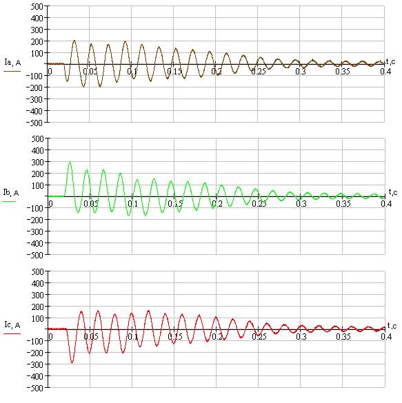
Figure 3 - Currents to 3 - m phases The figure shows that currents in phases B and C for the first time are maximum, which means it can be concluded that it is through their shock value are determined by shock current. According to the results of tests conducted the resulting vector current and voltage were calculated and built in Fig.4.
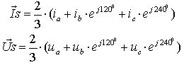
Figure 4 - The resulting vector current Is and voltage Us (animation made in the MP Gif Animator, is taken when updating pages, 8 personnel, 50 repetitions, 55.8 kb) The possible impact of shock current (iud = 310 A), trace damping aperiodic component is determine. The engine has reached nominal parameters through 0.25 seconds, idlehas been measured over 0.4 seconds.
The values of resulting vectors voltage and current are identified by the expressions:
ConclusionIn the course of research work conducting digital control system parameters of an asynchronous motor has been collected and configured. With its help a number of measurements, with high accuracy launchers characteristics AC machines are produced. The next phase is planned to determine the parameters of AD, study its performance in various operating conditions. NoteWhen writing this authosynopsis degree work has not been completed yet. Final completion: December 2008 Full text of work and materials on the topic can be obtained from the author or his head after that date. -To the top-© 2008 DonNTU |
|||||||
[Biography] |
||||||||
[Library] |
||||||||
[Links] |
||||||||
[Search] |
||||||||
[Individual task] |
||||||||
|
||||||||