Development and research of digital system of automatic control of an alternating voltage
Voltage regulation allows not only to increase quality of the electric power, but also to improve an industrial
process. It helps to reduce penalty, to increase its quality, to increase labour productivity and productivity
of mechanisms, and also to reduce energy losses.
Now problems of regulation of voltage have base in the form of regulating and compensating devices.
An application of regulating devices and their automation repays off the economy which is reached at
improvement of modes of voltage in electric networks and systems.
There are various ways of a voltage regulation. A variety of decisions depends from requirements on
the stability, control accuracy, parameters of loads, economics and other factors.
There are many regulators of an alternating voltage. Some of them are based on magnetic amplifiers. This
regulators are rarely applied in modern control systems, because this devices has some disadvantages, such as:
big dimensions and big weight.
Thyristors regulators are allows to reduce the physical sizes of the device, to decrease its cost and to reduce
electric power losses, but they has some disadvantages which limit their possibilities. First of all they brings
interferences in electric network, that quite often negatively affects in the work of TVs, radio receivers, tape
recorders. Secondly, they can be applied only for control of load with active resistance: electrolamp or a heating
element, and it is impossible to use them with load of inductive character, for example, electric motor or transformer.
The basic scheme of thyristors regulator of an alternating voltage is shown on fig. 1:
Figure 1 - Thyristor regulator of an alternating voltage
This regulator does not disseminate high power and has small dimensions.
Thyristor regulator [1] contains two trinistors, one of which opens in a positive half-cycle of mains voltage,
and another in the negative half-cycle.
Figure 2 - Thyristor regulator of an alternating voltage with gain-phase control
Advantage of this regulator are:
- it has smaller losses of voltage,
- it’s power increases twice in comparison with a regulator represented on fig. 1.
Transistors regulators doesn’t brings interference in an electric network and they can be applied for workload
management, as with active as with an inductive resistance. The regulator can be used for the control of:
- a brightness luminescence desk lamp,
- a temperature of heating of a soldering-iron,
- a speed of rotation of the electric motor of the fan or a drill, voltage on a transformer winding.
The basic scheme of transistor regulators of an alternating voltage [2] and [3] is shown in fig. 3:
Figure 3 - Transistor regulator of an alternating voltage
Loading power of the regulator [3] can be increase, if regulating transistors of the same type are
included in parallel.
The regulator [2] has some disadvantages:
- a resistor and a collector are connected together,
- a scheme cannot enter into deep saturation, and also it is unsuitable for remote control.
Transistor regulators of an alternating voltage [2] and [3] can be improved by using of a transistor
of opposite conductivity. Two-transistor regulator of an alternating voltage is shown on fig. 4:
Figure 4 - Two-transistor regulator of an alternating voltage
Using additional transistor provides reduction of nonlinear distortions at small output voltage and reduction
of losses at the maximum output voltage.
Since that transistors have different gains constant, the characteristics of a regulator shown on fig. 5,
differ considerably when current flows through VT1 (in the first half-cycle) and through VT2 (in the second half-cycle).
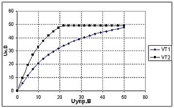
Figure 5 - Characteristics of regulator of an alternating voltage when current flows through
VT1 and VT2
It is necessary to receive identical currents of collectors of transistors for "alignment" of
characteristics. For this purpose it is necessary to increase a current of base of the transistor which
has the smaller value of h21. That’s why this scheme contains an additional diode VD3 and resistor a R4
which are included in a circuit management in parallel to a resistor R1 (fig. 6).
Figure 6 - Regulator of an alternating voltage with correction of the base current
Having corrected a base current, we receive practically identical currents of collectors of transistors VT1 and
VT2. Regulator characteristics are shown on fig. 7:
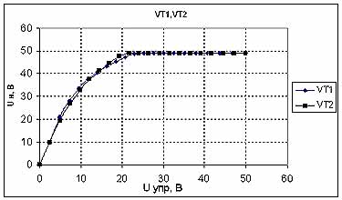
Figure 7 - Characteristics of a regulator with correction of a base current
The maximum losses of a voltage on a load can be gets from characteristics of a regulator which are taken
off at different positions of mobile contact of the variable resistor.
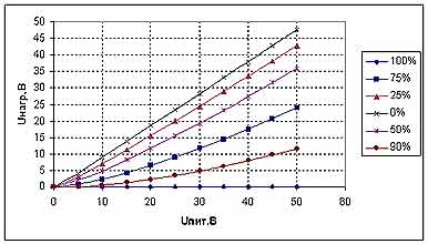
Figure 8 - Characteristics regulator of an alternating voltage when current flows through
the transistor VT1
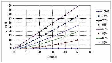
Figure 9 - Characteristics regulator of an alternating voltage when current flows through
the transistor VT2
For characteristics linearization it is necessary to use the nonlinear scheme of control or to use
the digital device to operate the regulator.
The device (4) can be improved fig.4, by adding of two dividers (R2, R3 and R4, R5), two transistors
of opposite conductivity (VT3 and VT4) and the operational amplifier.
Figure 10 - An alternating voltage Regulator
Using of the given regulator of an alternating voltage provides practically absolute linearity of
characteristics and can be applied in various devices, including the sound regulation.

The list of references
1. Transistor regulator of an alternating voltage with gain-phase management / the Electronic resource.
URL://www.electrik.org
2. Butov А „the Device of protection of low-power filament lamps“, Magazine "Radio" №2, 2004
3. Chekarov А „Regulator of voltage without interference “ Magazine "Radio", №11, 1999
© DonNTU 2008, Fesenko D.V.