|
Overview
The success of IEEE 802.11b wireless technology in the corporate environment is leading to more demanding usage of the 2.4-GHz ISM band. In this band, a proper deployment typically uses only the three nonoverlapping independent channels (1, 6, and 11 for the North American domain). However, several papers on the subject claim that the three-channel recommendation is overly restrictive and that up to four channels can be used in instances where maximum user and access point density or high aggregate network bandwidth is required. One of the most commonly cited papers on four-channel deployment comes from Cirond Corporation, which can be found here: http://www.cirond.com/whitepapers/FourPoint.pdf
We disagree with this assertion and will use this paper to explain some of the issues and problems that can arise with a four-channel deployment scheme.
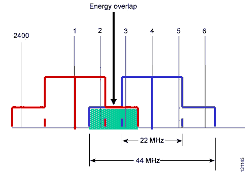
802.11 RF Channel Specification
The IEEE 802.11 standard establishes several requirements for the RF transmission characteristics of an 802.11 radio. Included in these are the channelization scheme as well as the spectrum radiation of the signal (that is, how the RF energy spreads across the channel frequencies). The 2.4-GHz band is broken down into 11 channels for the FCC or North American domain and 13 channels for the European or ETSI domain. These channels have a center frequency separation of only 5 MHz and an overall channel bandwidth (or frequency occupation) of 22 MHz. This is true for 802.11b products running 1, 2, 5.5, or 11 Mbps as well as the newer 802.11g products running up to 54 Mbps. The differences lie in the modulation scheme (that is, the methods used to place data on the RF signal), but the channels are identical across all of these products.
Figure 1 shows the North American channelization scheme.
 The level of RF energy that crosses between these channels determines interference. Radios do not have an exact edge to their channel, and energy spreads beyond the edges of the channel boundaries. However, the overall energy level drops as the signal spreads farther from the center of the channel. The 802.11b standard defines the required limits for the energy outside the channel boundaries (+/- 11 MHz), also known as the spectral mask.
Figure 2 shows the 802.11b spectral mask, which defines the maximum permitted energy in the frequencies surrounding the channel's center frequency (or fc).
Figure 2 802.11b Spectral Mask

The energy radiated by the transmitter extends well beyond the 22-MHz bandwidth of the channel (+/- 11 MHz from fc). At 11 MHz from the center of the channel, the energy must be 30 dB lower than the maximum signal level, and at 22 MHz away, the energy must be 50 dB below the maximum level. As you move farther from the center of the channel, the energy continues to decrease but is still present, providing some interference on several more channels.
The worst-case scenario is a 100-mW transmitter and a good receiver. The Cisco Aironet 350 radio transmits at 100 mW, or +20 dBm. The 350 receiver can receive signals as low as -85 dBm (and even down to -93 dBm at 1 Mb).
Note: The more negative the receiver sensitivity number, the lower the signal level necessary to properly decode the signal.
Therefore, at 11 MHz away, the energy from the transmitter is 35 dB below the maximum (100 mW/20 dBm), putting it at a possible -15 dBm. Move another 11 MHz away, and the signal level is 50 dB below the maximum (100 mW/20 dBm or -30 dBm), which is still over 50 dB higher than the receiver needs to receive properly. In short, the receiver still hears the signal, even at 22 MHz away.
Figure 3 shows a four-channel system.
Figure 3 Four-Channel System
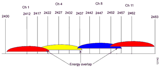
The energy overlap between the channels does not appear to be significant. However, as discussed earlier, this overlap is at the +/- 11-MHz and 22-MHz points, where the energy is still quite strong. If we use the transmitter mask to show the possible energy that could be available, we see that there is significant energy from channel 1 in the area for the receiver of channel 4 to hear (see Figure 4).
Figure 4 Transmitter Mask Showing Available Energy
Deploying Access Points
The counter-argument to the position that a device on channel 4 will hear a device on channel 1 involves the concept of physical separation. It is possible that proper placement of the access points provides enough physical separation between the cells so that the energy level at the edge of each cell is low enough so as not to generate interference. This concept is shown in Figure 5.
Figure 5 Positioning Access Points to Avoid Interference

For an environment with a very low user density, this assumption could be true. In a site survey, interference between the access point on channel 4 and the client on channel 1 would not likely be noticed. But this is not the case in a high user density system in which the four-channel argument is intended to be used. Typically, access point coverage cells are not overly large in a high user density environment, permitting fewer users per access point (resulting in higher bandwidth per user). As a result, the range of the client transmitter is only slightly less than that of an access point in this deployment scheme. For this case, however, we can assume that the client has 50 percent of the access point transmitter range (keeping in mind that the larger antenna on the access point improves the receive signal, enabling it to still hear the client).
Figure 6 shows that the energy of the channel 1 client transmitter is physically located very close to the channel 4 client receiver and will very likely cause interference.
Figure 6 Interference between Clients

This proximity is important because 802.11 specifies the protocol using carrier sense multiple access (CSMA), meaning listen before transmitting. In this case, channel 4 clients refrain from transmitting until the client that is transmitting on channel 1 is finished. In a system with few users, this is probably not a problem. However, as the number of clients increases, so does the possibility of holdoffs.
This scenario also increases the likelihood of collisions, resulting in retries for both clients and decreasing the efficiency of the WLAN. If the cross-channel signal is low enough not to be decoded as a valid 802.11 signal, it is considered noise. This is when collisions start to occur. The noise is strong enough that the desired signal gets corrupted, and the packet needs to be retransmitted. Overall, this is much worse than a holdoff because the device transmits the packet twice (or more) rather than waiting for a clear time and sending it once.
Moving to 802.11g
The spectral efficiency (that is, the way in which the frequencies surrounding the center of the channel are used) for the orthogonal frequency division multiplexing (OFDM) modulation used in 802.11g devices is much worse than that for the complementary code keying (CCK) modulation used in 802.11b devices. Figure 7 shows the transmitter specification for 802.11g.
Figure 7 802.11g Transmitter Specification

At 11 MHz from the center, the transmitter energy level is only 20 dB below the maximum (as opposed to 35 dB for 802.11b), and at 22 MHz away, the energy is only about 30 dB below (as opposed to 50 db for 802.11b). Even as far out as 40 MHz, the energy is still only 40 dB below the maximum. Using the four-channel scheme here results in an overlap as shown in Figure 8. Notice how much greater the energy overlap is when using 802.11g.
Figure 8 Energy Overlap in 802.11g Four-Channel Scheme

Adding Voice
With the increased number of 802.11 voice devices being used on WLANs, sharing the network with both data and voice is rapidly becoming a primary concern. There is a drastic difference between voice over WLAN and data over WLAN. Holdoffs, retries, and other factors that result from interference are not a significant issue for data users. However, dropouts and delays cause real problems for voice users. Deploying a four-channel system with voice devices will very likely result in a severe degradation of voice quality near the edges of adjacent cells when other clients are in the area.
Test Results
Cisco performed tests to see the interference in a four-channel environment. The tests were conducted with four Cisco Aironet 1200 access points and four Cisco Aironet 350 clients, all running 802.11b at 11 Mbps. To help simulate the physical separation between devices, the access points and clients were set at 5-mW transmit power and spaced about 10 feet apart.
The throughput was measured by the average of all four clients simultaneously passing a 50-MB file five times. In all combined tests there was one client to each of the four access points. In the stand-alone test for benchmark comparisons, all four access points and all four clients were on. However, only one client was in the process of sending a 50-MB file using FTP.
Testing included two different scenarios:
1. Four North American access points, two using channel 1, the third using channel 6, and the fourth using channel 11
Note In this model, the first two access points had to share the RF because they were on the same channel.
2. Four North American access points using channels 1, 4, 8, and 11
Table 1 displays the results of the two tests. Note that even when two access points shared channel 1, the overall performance was greater than in the four-channel scenario. This is because the CSMA protocol created a holdoff when the clients on the same channel decoded that the interference was another 802.11 signal. In the four-channel scenario, the client could not decode the interfering signal, reacted as if it was low-level noise rather than a holdoff, and sent the packet. This resulted in a collision and a retransmission on both clients.
Table 1 Result Summary Showing Average Throughput per Client
| Channels | Throughput (KB) |
| 1, 1, 6, and 11 | 601.1 |
| 1, 4, 8, and 11 | 348.9 |
Conclusion
Many have long recommended a three-channel approach to provide nonoverlapping channels. We still recommend such installations for 2.4-GHz WLANs, for both 802.11b and 802.11g technologies. A four-channel scheme can cause severe issues when the system is brought online and the number of users starts to increase.
In a four-channel design, the signal of one device is noise to another device. Even in a design where a channel 1 cell would never overlap a channel 4 cell, for example, you must still account for clients transmitting that are not in the same location as the access point. By looking at only the access points, you are ignoring the majority of radios in your network. Virtually all new radio deployments support 802.11g and/or 802.11a and thus OFDM, which has much more sideband energy than 802.11b.
If you design a system with four channels, the risk of interference between cells greatly increases, resulting in poor performance and lower throughput. As the volume of users and bandwidth needs increase, problems will slowly arise, making it necessary to resolve the issue at a later date. Start by using three nonoverlapping, noninterfering channels.
CCSP, the Cisco Square Bridge logo, Cisco Unity, Follow Me Browsing, FormShare, and StackWise are trademarks of Cisco Systems, Inc.; Changing the Way We Work, Live, Play, and Learn, and iQuick Study are service marks of Cisco Systems, Inc.; and Aironet, ASIST, BPX, Catalyst, CCDA, CCDP, CCIE, CCIP, CCNA, CCNP, Cisco, the Cisco Certified Internetwork Expert logo, Cisco IOS, Cisco Press, Cisco Systems, Cisco Systems Capital, the Cisco Systems logo, Empowering the Internet Generation, Enterprise/Solver, EtherChannel, EtherFast, EtherSwitch, Fast Step, GigaDrive, GigaStack, HomeLink, Internet Quotient, IOS, IP/TV, iQ Expertise, the iQ logo, iQ Net Readiness Scorecard, LightStream, Linksys, MeetingPlace, MGX, the Networkers logo, Networking Academy, Network Registrar, Packet, PIX, Post-Routing, Pre-Routing, ProConnect, RateMUX, Registrar, ScriptShare, SlideCast, SMARTnet, StrataView Plus, SwitchProbe, TeleRouter, The Fastest Way to Increase Your Internet Quotient, TransPath, and VCO are registered trademarks of Cisco Systems, Inc. and/or its affiliates in the United States and certain other countries.
All other trademarks mentioned in this document or Website are the property of their respective owners. The use of the word partner does not imply a partnership relationship between Cisco and any other company. (0406R)
Copyright © 2004 Cisco Systems, Inc.
All rights reserved.
|