| Autobiography |
| DonNTU Master's portal |
| ENG | РУС | УКР| | |

|
Meznikova KatyaFaculty: Electromechanics and automaticsChair: Mining equipment Speciality: The mining equipment Subject of master's thesis: Increase of a technological level of remote haulage system of shearer UKD 200-250 Supervisor: Candidate of Technical Science, Professor Semenchenko Anatoliy |
Abstract on a theme of master's work |
|
|
Object of research - the remote haulage system with frequency regulation of speed of a shearer UKD 200-250. The purpose of work: To develop mathematical model for a substantiation of parameters of remote haulage system of shearer with the frequency converter. INTRODUCTIONBy extracting seam thickness of 0.8-1.2 m the question of coal quality improvement becomes a problem of today. Creation and introduction of highly – reliable shearers should provide improvement of coal quality. At the moment the shearer UKD 200-250 is the most actual for extraction of thin seam. Service factor of combines UKD 200-250 is 0.65, and service factor of other combines for thin seams does not exceed the level of 0.3. Combine UKD 200-250 is equipped with remote haulage system with chain hauling block. Parameters simulation and optimization of remote haulage system have the great practical importance as it is necessary to raise their speed characteristics and to expand an application field using a frequency - adjustable whim. Task of the given project is development of correct dynamic and mathematical models of working processes of remote haulage system with a frequency - adjustable whim 1 DEVELOPMENT OF MATHEMATICAL MODEL OF REMOTE HAULAGE SYSTEM WITH A FREQUENCY - ADJUSTABLE WHIMCombine UKD 200-250 is intended for winning seams of 0-35 degrees with thickness of 0.85-1.3 m. The combine rests on the conveyor with four noncontrollable supporting mechanisms and on ground with one noncontrollable supporting mechanism. The combine has 1 electric motor for both whim effector subsystems and individual electric motors for subsystems of haulage. The general view of a combine is presented in figure 2.
1 – the electric motor for whim effector subsystems; 3, 4 - the basic and ranging arm of whim effectors subsystems; 5, 6 – goaf and longwall supporting mechanisms; 7 - the supporting mechanisms on ground; 8 – effectors 15 - hydrojacks of a suspension mount and moving effector subsystems; 17 – a portal part of case-shaped subsystems. To build a mathematical model of remote haulage system it is necessary to develop the dynamic circuit of a combine (fig. 2).
Let's specify the conventional signs: Мдв1, Мдв2 – the leverage of the 1-st and 2-nd electric motors; φдв1, φдв2 – rotational angles of rotors of 1-st and 2-nd electric motors; Iдв1, Iдв2 – the moment of inertia of electric motors rotors; Iзв – the moment of inertia of a drive chain sprocket; Ср – factor of reducer rigidity of whim of remote haulage system; βp – factor of reducer resistance; Сц – factor of chain rigidity; βц – factor of chain resistance; φзв1, φзв2 – rotational angle of drive chain sprocket; m1– mass of a hauling chain from drive chain sprocket 1 to combine; m2 – mass of a hauling chain from drive chain sprocket 1 to drive chain sprocket 2; m3 – mass of a hauling chain from drive chain sprocket 2 to combine. Let's place forces which operate on a combine and chain links.
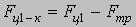
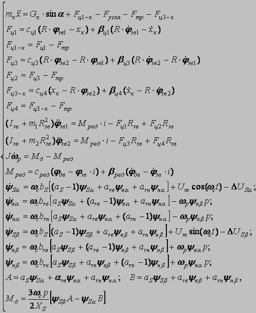
The mathematical model consists of the following cooperating modules: - Mathematical model of the frequency - adjustable asynchronous electric motor; - Mathematical model of remote haulage system which includes a whim, hauling unit and a shearer; - Mathematical model of formation of resistance forces against a movement of a combine. Mathematical model of the drive chain sprocket 1:
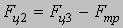
Mathematical model of the drive chain sprocket 2:
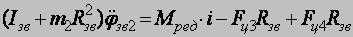
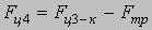
Model of a combine:
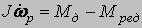
Model of the engine:
The mathematical model of the asynchronous engine is developed on the basis of researches of Parkа-Goreva.
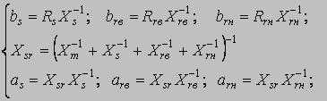
Rs, Xs - active and inductive resistance of a phase of a stator winding; Rrв, Rrн - active resistance of phases of the top and bottom cages of a rotor, respectively; Xrв, Xrн - inductive resistance of dispersion of the top and bottom cages of a rotor, respectively; Rm, Xm - and inductive resistance of mutual induction; Rc, Xc - and inductive resistance of a power line. Design factors:
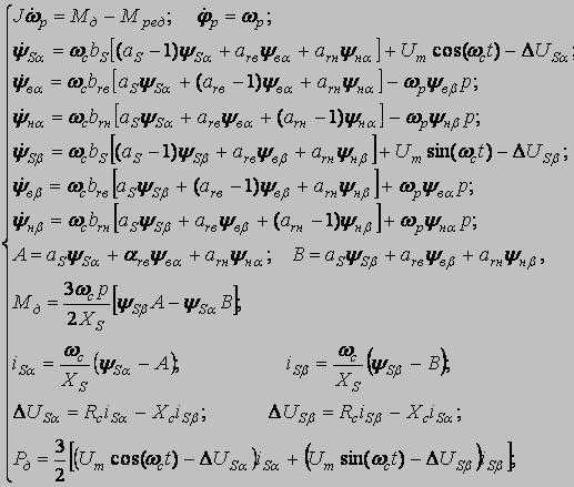
bs, brв, brн - factors of relative resistance; as, arв, arн - factors of relative reactance. The basic equations MM [3]:
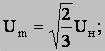
φр, ωр - rotational angle and angular rate of rotor rotation; J - the inertia moment of a rotor of the engine; Mд - the electromagnetic moment of the engine; Mс - the moment of loading on a motor shaft; ψSα, ψSβ, ψнα, ψнβ, ψвα, ψвβ - components of linkage vectors; ωс - angular rate of a magnetic field; t - current time; ΔUSα, ΔUSβ - vector projections of a power failure of stator on an axis α and β in a view of a power line influence; iSα, iSβ - currents of stator in a projection on axes α and β; Um - amplitude of a voltage in a phase;
Uн - rated voltage of a network (linear); р - number of pairs poles of the electric motor; Рд - the active capacity consumed by the electric motor. In a general view the system looks like:
2 MODELLING OF AN ENGINE START-UPWith the help of program Mathcad it is necessary to simulate process of asynchronous engine running. Let’s set the catalogue data, such as efficiency and the moment of inertia: Крd=0.92 J=1.23
and parameters of an equivalent circuit - active and inductive resistance of a phase of a winding stator, inductive resistance of mutual induction, active and inductive resistance of the top and bottom cages of a rotor:
Rs=0.052 Torque: m0=1500 Set entry conditions and calculate parameters of the right parts of the differential equation:
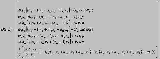
bs=Xs-1·Rs Calculation of the right parts of differential equation: 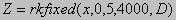 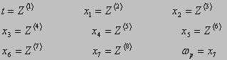 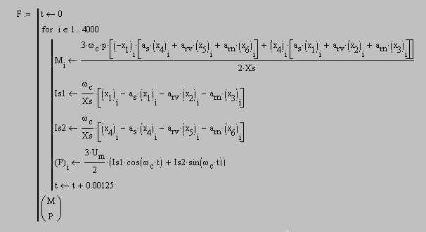
THE CONCLUSIONIn the given project the mathematical model for a substantiation of parameters of remote haulage system of shearer with the frequency converter has been developed. By the instrumentality of the program Mathcad process of work of the asynchronous engine run is simulated. REFERENCES
Now master's degree work is in a state of development. Complete its ending is planned on at end December, 2009. |
|
| DonNTU | Master's portal | Autobiography | |