Research of methods of integration to CAD-systemsIntroductionAt the moment there are many software products that provide three-dimensional design and modeling sites. They allow you to create almost any kind of complexity and provide a model for this large number of tools. This reduces the design time model and allows more emphasis on the calculation of its characteristics, which is a very important task in mechanical engineering. Therefore, the correct allocation of time designing and modeling can be a recipe for success. However, in many major CAD and CAE systems, the main emphasis is on modeling or projecting. Thus, the creation of models in CAE system can take a long time. The majority of the CAD system does not allow it created a model in other systems. The main problem is the complexity of data format, which is stored and processed by the model. Therefore there is a need for interaction between CAD and CAE systems by integrating them and getting all the necessary data. This becomes possible due to the fact that CAD-systems offer opportunities to third-party applications to run on both the interface and data. Actuality of themeAt the moment, there are several major design systems with different specialization. But the lack of linkages between them leads to what is practically impossible to produce transfer models from one package to another. Therefore it is urgent the question of organizing the interface between the most popular systems, and especially between the highly specialized systems. The presence of this interface would better organize the process of designing and modeling, as will be possible to divide the main task into stages, each of which can be met in the most appropriate system design. Purpose and tasks- study and comparison of modern CAD systems, as well as methods of integrating them with programming languages; - integration in SolidWorks; - integration into AutoCAD. Overview of CAD-systemsComputer-aided design (computer-aided design - CAD) is a technology consisting in the use of computer systems to facilitate the creation, modification, analysis and optimization projects. Thus, any program that works with computer graphics, as well as any application that is used in engineering calculations, refers to computer-aided design. In other words, the set of CAD range from geometric programs for working with forms to specialized applications for analysis and optimization. Between these extremes fit program for the analysis of tolerances, the calculation of the masses - inertial properties, the method of finite element modeling and visualization of analysis results. The most basic function of CAD - the definition of the geometry of the design (details of the mechanism, architectural elements, electronic circuits, building plans, etc.), since the geometry determines all subsequent stages of product life cycle. For this purpose, commonly used system for creating working drawings and geometric modeling. That is why these systems are usually considered as computer-aided design systems. Moreover, the geometry defined in these systems can be used as a basis for further operations in the CAE and CAM systems. This is one of the most significant advantages of CAD, allowing to save time and reduce errors related to those with the need to determine the geometry of the structure from scratch every time it is needed in the calculations. One can therefore argue that a system of automated design and working drawings of geometric modeling systems are the most important components of computer-aided design [1]. SolidWorksSolidWorks - computer-aided design, engineering analysis and manufacture of products of any complexity and purpose. SolidWorks is the core of an integrated set of enterprise automation, through which the support of the product life cycle, in accordance with the concept of CALS-technologies, including bi-directional data exchange with other Windows-based applications and the creation of online documentation [3]. From the beginning of the SolidWorks Corporation has endeavored to create the design system "medium" level. It should be noted that this task was successfully accomplished. Moreover, according to many leading experts in this field, SolidWorks 2004 version is already much higher than "medium" level, although she, like all previous versions, based on the same geometric kernel Parasolid, which is based on such "hard" engineering system as Unigraphics. A possible version of SolidWorks 2009, of course, more widely [2]. 
Process of creating detail in SolidWorks. 4 frames with 1 second delay. 350 * 250. Made in в Adobe ImageReady UnigraphicsPackage Unigraphics is a universal medium-aided design and manufacturing of industrial enterprises in various sectors. Approach to product development in the Unigraphics reflects an iterative process that allows to design and analyze a fully electronic model for as long as she would not meet the necessary technical requirements. This is facilitated by a powerful core of a hybrid model, allowing the constructor has a choice between technologies parametric modeling using solids, parameterized model elements, surfaces and wire geometry. You can combine the parametric or variational model is not parameterized data in any representation of the product. The package is Unigraphics market CAD / CAM / CAE systems. It allows you to: - Computer-Aided Design (CAD); - Machining (CAM); - Reverse engineering (CAE); - Designing and processing of products from metal sheet (Sheet Metal). AutoCADAutoCAD - a 2-and 3-dimensional computer-aided design and drafting company Autodesk. AutoCAD family of products is one of the most popular CAD systems in the world. Company is developing a system of Autodesk CAD AutoCAD c 1982, ie more than 26 years. AutoCAD provides all the necessary tools to design drawings: a broad set of graphics primitives, tools for automatic dimensioning, hatching, shading, and tools for copying, rotating, scaling, created objects, functions for layout designs and their subsequent printing, the ability to create your own libraries of drawings and frequently used items. AutoCad uses the kernel Acis - object-oriented geometric modeling package, developed by Spatial Technology for use as a geometric framework in applications to three-dimensional modeling. Acis provides a tool with an open architecture for frame, surface and solid modeling with a common, unified data structure. [5] Methods of integrationThe basis of modern CAD systems are specialized geometric modeling kernel. Kernel - a set of mathematical functions, which is designed for accurate mathematical representation of three-dimensional shape of a product and management of this model. Obtained with the help of geometric data using computer-aided design systems (CAD), technological preparation of manufacture (CAM) and engineering analysis (CAE) to develop structural components, assemblies and products. Designer has access to the functions of the kernel of the corresponding CAD system through a graphical user interface. Thus, the kernel is very important. Therefore, it is sometimes called the "motor" of the system design. That is, it determines its functionality and performance. The interaction of the nucleus of an integrable system design and application is done through a special API. As a rule, API provides all the necessary tools to obtain current data from the CAD system, as well as their changes. There are two possible transfer of control from CAD system to integrable application: - A direct call to the application through a graphical interface system; - Automatic call to the application when certain events. Integration in SolidWorksProblemWe need to carry the transfer model created in the system of SolidWorks, a CAE-system MDesign 11.0 (module SHAFT). SHAFT module is designed to calculate the characteristics of the shaft, which is given by a set of hollow or solid levels of different forms. SHAFT module is shown in Figure 1. 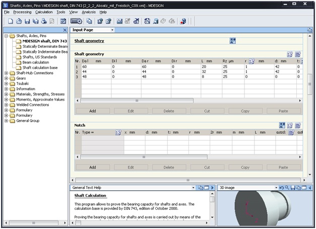 Fig.1 The main form module MDesign SHAFT The process of creating a model of the shaft is shown in Figure 2. 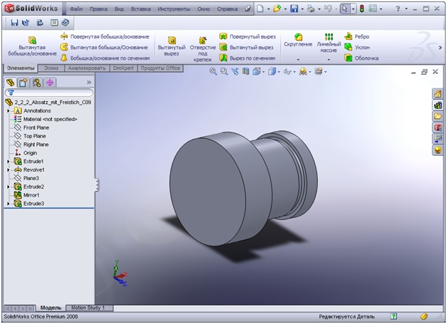 Fig.2 Creation of a model of the shaft in SolidWorks Using SolidWorks to design a functional model with subsequent transfer into the system to perform calculations MDesign increase productivity and enhance the ability of the module SHAFT to create the model and the calculation of its characteristics. Algorithm analysis modelTo arrange the transfer of models from the system in SolidWorks system MDesign, requires a preliminary analysis of the model. The objectives of the analysis are: - Error checking in the model of the shaft (ie, the shaft has a form that can not be set in the module MDesign SHAFT); - In error - message with an indication of the incorrect section of the shaft; - Save the model of the shaft in a format that can be downloaded module MDesign SHAFT. The result of the analyzer is a model of the shaft, which must match exactly with the model displayed in SolidWorks. Program InterfaceManagement of the program is through the toolbar (Figure 3), which has the following buttons: 1. Analysis and Preservation of the current model. 2. Analysis of the current model. 3. Starting CAE-systems MDESIGN Shaft. 4. Dialogue options (Fig. 4). 5. Help.  Fig.3 Toolbar 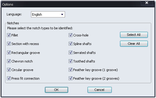 Fig.4 Dialog options ConclusionsIn carrying out this work have been studied modern CAD systems, explored the integration of them, and made the process of integration in the CAD-system SolidWorks. The resulting program is designed to export data from a SolidWorks in the module MDesign SHAFT. At the moment the program is in testing. Planned expansion of the functional by increasing the number of analyzed operations and facilities SolidWorks. In addition, the planned execution of integration into the system, AutoCAD and Unigraphics. In the course of work were explored various methods of integration in the CAD-system, as well as the various algorithms of interaction with geometric kernels of these systems. These skills were used in writing the integration program, which will help save time and effort for users of SolidWorks and MDesign SHAFT. Literature1. Ли К. Основы САПР (CAD/CMA/CAE). – СПб.: Питер, 2004. – 560 с. 2. Прерис А.М. SolidWorks. Учебный Курс.- СПб.: Питер, 2006. – 528 с. 3. Сайт «SolidWorks Russia» [электронный ресурс]: http://www.solidworks.ru/products/solidworks/ 4. Сайт «Википедия» - [электронный ресурс]: http://ru.wikipedia.org/ 5. Краснов М. Unigraphics для профессионалов – М.: Лори, 2004. – 319 с 6. Сайт «Sapr RU» - [электронный ресурс]: http://www.sapr.ru/article.aspx?id=6645&iid=272 7. Сайт «Cad DP UA» - [электронный ресурс]: http://www.cad.dp.ua/obzors/karnel.php 8. Сайт «MaiRu» - [электронный ресурс]: http://www.mai.ru/~apg/Volume7/Number15/bur715.pdf 9. Сайт «IntKiev» - [электронный ресурс]: http://www.int.kiev.ua/technol/ug_rus4.htm 10. Сайт «CADALYST» - [электронный ресурс]: http://www.cadalyst.com |
 |
Fedorenko EvgenyFaculty: Computer science |