Eckart Hartmann, Analog Devices
Источник: www.analog.com/...
Introduction
An electrocardiogram (ECG) is a recording of the electrical activity on the body surface generated by the heart. ECG measurement information is collected by skin electrodes placed at designated locations on the body. The ECG signal is characterized by six peaks and valleys labeled with successive letters of the alphabet P, Q, R, S, T, and U (Figure 1).

Figure 1. Form of ECG signal.
This article suggests some ideas for a low-cost implementation of an ECG monitor. Its configuration is envisaged for use with a personal computer (PC). Although this article is written with patient safety in mind, any ideas presented are not by themselves necessarily compatible with all system safety requirements; anyone using these ideas must ensure that, in a particular design, the design as a whole meets required safety criteria.
First we provide an overview of typical analog ECG topology. Then a circuit is proposed which performs analog-to-digital conversion, digital filtering, and digital amplification—all by using a Micro Converter—an integrated “system on a chip” that combines an A/D converter, microcontroller, and flash memory. The article goes on to discuss considerations in the choice of components and programming of the Micro Converter.
Requirments for the kardiograph
The front end of an ECG must be able to deal with extremely weak signals ranging from 0.5 mV to 5.0 mV, combined with a dc component of up to ±300 mV—resulting from the electrode-skin contact—plus a common-mode component of up to 1.5 V, resulting from the potential between the electrodes and ground. The useful bandwidth of an ECG signal, depending on the application, can range from 0.5 Hz to 50 Hz—for a monitoring application in intensive care units—up to 1 kHz for late-potential measurements (pacemaker detection). A standard clinical ECG application has a bandwidth of 0.05 Hz to 100 Hz.
ECG signals may be corrupted by various kinds of noise. The main sources of noise are:
- power-line interference: 50–60 Hz pickup and harmonics from the power mains
- electrode contact noise: variable contact between the electrode and the skin, causing baseline drift
- motion artifacts: shifts in the baseline caused by changes in the electrode-skin impedance
- muscle contraction: electromyogram-type signals (EMG) are generated and mixed with the ECG signals
- respiration, causing drift in the baseline
- electromagnetic interference from other electronic devices, with the electrode wires serving as antennas, and
- noise coupled from other electronic devices, usually at high frequencies.
For meaningful and accurate detection, steps have to be taken to filter out or discard all these noise sources.
Typical ecg signal chain
Figure 2 shows a block diagram of a typical single-channel electrocardiograph. In that chain it is apparent that all filtering is done in the analog domain, while the microprocessor, microcontroller, or DSP is used principally for communication and other downstream purposes. Thus the powerful computational properties of the digital core are not readily available to deal with the signal in its essentially raw state. In addition, sophisticated analog filters can be costly to the overall design due to their inflexibility—and the space, cost, and power they require.
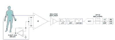
Proposed circuit
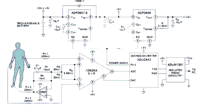
The signal chain can be simplified by using an ADuC842 Micro Converter, which allows the ADC, filters, and microprocessor to be combined in a single integrated circuit. Additional advantages are flexibility of filter implementation and isolation in the digital domain. The proposed system design is shown in Figure 3.
Analog input processing
The analog front end uses the typical approach with an instrumentation amplifier (IA) and a right leg common-mode feedback op amp. The IA is the AD620, a low cost, high accuracy instrumentation amplifier, with excellent dc performance: CMR>>100 dB to nearly 1 kHz, 50-μV max offset voltage, low input bias current (1 nA max), and low input voltage noise (0.28 μV from 0.1 Hz to 10 Hz).
The AD620 requires only a single external gain-setting resistor, RG. Resistors R2 and R3 change the normal gain equation to [Gain = 1 + 49.4 k/RG + (49.4 k/2)/22 k]. To avoid output saturation, the usable gain is limited by the output swing and the maximum input voltage to the IA. With a ±5-V power supply, the output swing of the AD620 is about ±3.8 V; and the maximum input is ±5 mV plus a variable normal-mode dc offset of up to±300 mV, allowing a maximum gain of 12.45. Here, the gain is conservatively set to 8 (±1%), using RG = 8.45 kΩ.
The op amp used in the right-leg common-mode feedback circuit is the OP97, a low power, high precision operational amplifier with extremely high common-mode rejection (114 dB minimum). This circuit applies an inverted version of the common-mode interference to the subject’s right leg, with the aim of canceling the interference. The op amp has a voltage gain for the common mode voltage of 91 [viz., R4/(R2 || R3) = 1 MΩ/11 kΩ], with a 1.6-Hz roll off and a low-pass cutoff at about 160 Hz for stability [f–3 dB = 1/(2π* (10 kΩ * 0.1 μF)].
Patient safety
In addition to the digital isolation and the safe power supply, the series resistors, Rx1, Rx2, and Rx3, provide protection for the patient—in order to comply with AAMI (Association for the Advancement of Medical Instrumentation) standards for safe current levels (see References). These standards require that rms ground currents or fault current from the electronics must be less than 50 μA.
Signal processing
The ADuC842 Micro Converter is well suited for the main signal processing tasks. It features a fast, 12-bit ADC and other high-performance analog peripherals, a fast 8052 microprocessor core, integrated 62KB flash memory for code, and several other useful peripherals, as shown in Figure 4.
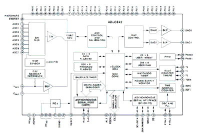
The key components of the Micro Converter for this design are the ADC and the 8052 core. The ADC converts the analog output of the instrumentation amplifier to a digital signal. The software written for the 8052 core processes the digitized signal to produce the data for the ultimate ECG trace. As in many Micro Converter designs, the software includes both complex high level code written in C and time sensitive routines written in assembly code. In this case, the implementation of band-pass filters and notch filters is in C, while the ADC is controlled by assembly code. Assembly code, combined with converter speed, enables the accumulation of multiple samples, enhancing the effective resolution of the ADC well beyond its normal 12 bits.
Gain
Signal gain is always an important consideration in an ECG signal chain. In the above-described design, it depends on a number of factors. The analog gain is set to 8*, as discussed previously. Next, a gain of 64* results from accumulating 64 measurements of this signal. Next there is a signal loss of 8* from the code iBIn = iAdc0>>3;, and finally, a gain of 4* twice from the scaling of the first two band-pass-filter equations. This results in a total gain of G = (8 * 64/8) * 4 * 4 = 1024, which is typical of analog ECG circuits.
Conclusion
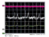
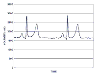
Figure 8 shows results for a subject connected in Einthoven lead I configuration. As can be seen, good results are achieved despite the simplicity of the electronic hardware used. The article demonstrates that significant improvements can be achieved with simple hardware combined with attention to software. The improvement in this example is by no means at the optimum level; it should be possible for a dedicated designer to significantly improve the results. Additional improvements could be made if code with different filter frequencies or other special characteristics were to be implemented. The code memory of the ADuC842 is flash based, allowing such customizations to be made after a product using it is manufactured—or even as the patients’ needs change. An ultimate result could be a compact, inexpensive ECG for a potentially large-volume market.
References
- Webster John G., Medical Instrumentation. Application and Design. 3rd edition, Wiley, 1998.
- Firth J. and Errico P., “Low-Power, Low-Voltage IC Choices for ECG System Requirements,” Analog Dialogue, Volume 29, Number 3, 1995.
- AAMI, American National Standard, Safe Current Limits for Electromedical Apparatus (ANSI/AAMI ES1-1993). Association for the Advancement of Medical Instrumentation, 1993.
- AD620 Data Sheet revision F. Analog Devices, Inc., ©2003.