
Speciality: the System programmer
Theme of research works:
"Working out and research of methods of testing of the FPGA-device with use of technology Boundary-Scan"
The supervisor of studies: Zinchenko Jury Evgenievich
The Abstract on the topic
"Working out and research of methods of testing of the FPGA-device with use of technology Boundary-Scan"
Introduction
When were the integrated circuit, there was a problem of their diagnosis (in the U.S. in 1959). Diagnosis required the use and development boards. When there were large and very large integrated circuits, has ceased to be a place for access to integrated circuits for their diagnosis.
Topical issue
At diagnosis, there are many contact methods for testing integrated circuits. Technology contactless scanning boundary-scan allows you to test IС, which are physically inaccessible. Thus the high test coverage. The tested IС should be testability - meet the standard IEEE 1149.
Practical innovation
The mechanism of Boundary-Scan, which corresponds to the digital standard IEEE 1149.1 test LSI and VLSI. A brief review of software and devices complexes of some firms, which are designed for testing integrated circuits enabled for Boundary-Scan.
The main content of
The first version of the standard testing devices with limited access to the findings of the integrated circuit - Boundary-Scan, first appeared in 1990, and received the name that has been preserved and today - IEEE 1149.1. The standard of this technology is also called a Test Access Port and Boundary-Scan Architecture (test access port and boundary scan architecture). The project was developed by an international panel of experts, which was known as JTAG (Joint Test Action Group - a united group of developing methods for testing), so the standard boundary scan technology is better known under the name of the abbreviations [4].
According to the standard IEEE 1149.1, the so-called Boundary-Scan-IС, shall be equipped with four mandatory elements:
- TAP-port which consists of four mandatory signals, and fifth at the discretion of the developers directly to the card (TCK - contact synchronization mechanism work Boundary-Scan; TMS - contact select the test mode; TDI - contact input test data; TDO - Test Data Output contact ( is constantly in the third condition, except for the regime shift); / TRST - Contact asynchronous reset the TAP-controller (may not be present)).
- TAP-Controller acts as one of the important elements of managing all of the technology of Boundary-Scan;
- IR (Instruktion Register of eng. - Register Team) - The first group of registers, in which the mandatory standard should be at least one instruction register (RC);
- DR (Data Registers of the main characteristics. - Data register) - the second group of registers, according to the standard must include a minimum two registers: the Register Bypass (RB, also sometimes referred to as shunt-register), Register of Boundary-Scan.
Such a minimal set of elements required by standard IEEE 1149.1. Other registries, which can complement the group as IR, so-DR at the discretion of developers cards are also accepted to create standards [2] [3].
In order to get good test coverage is not necessary that all the components on the board have JTAG-interface. For example, a lot of blocks, which consist of not scanning components (cluster), can test, despite the lack of direct access to the boundary-scan.
Figure 1 depicts the architecture of Boundary-Scan. In the TAP-controller serves 2 (3) signal by which the controller determines the appropriate mode of operation of the circuit. TAP-controller is an automaton with a finite number of vertices. In this article, his work will not be discussed in detail.
The basic principle of Boundary-Scan is that around the IC in the design phase are the cells Boundary-Scan, which comprise one of the mandatory data registers - the Register of Boundary-Scan. Boundary-Scan cells are located directly between the external pin and the functional core of IC. IC, surrounded by such a design compliant with IEEE 1149.1 and subject to the test with the help of technology Boundary-Scan. It is also necessary that each previous test output TDO was connected with the next test input TDI, then the chain of registers Boundary-Scan scans all the IC will be continuous (figure 2). The ideal situation is when all the IC, located on the motherboard supports this standard. But if so, it must resort to in-circuit testing for testing integrated circuits, which are not scanned.
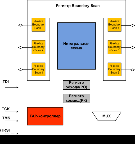
Figure 1 – Animation (15 frames, 7 cycles, 309 Kb). Architecture of technology Boundary-Scan
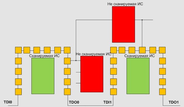
Figure 2 – the Payment with not scanned ИС
For maximum use of all privileges Boundary-Scan reliable working out of the software, and also auxiliary hardware maintenance is required.
Today in the world market in this area four representatives of the USA and Europe which deliver hardware-software complexes (ASSET InterTech Inc are in the lead. And CORELIS Inc – the USA; GOEPEL Electronic – Germany; JTAG Technologies – the Netherlands). Such workings out are called BS-testers. [1]
Here a number of hardware-software complexes which deserve trust of the users:
- ScanWorks firms Asset InterTech
- ScanExpress firms Corelis
- ProVision firms JTAG Technologies
- onTAP firms Flynn Systems
- XJTAG firms XJTAG
- SourceWizard and ScanMaster firms Acculogic
Distinctions between systems concern in means of working out of tests and their debuggings, to convenience and efficiency of search of defects by results of received diagnostics of malfunctions, means of the analysis of levelfitness testing and completeness of a covering of malfunctions:
- Automation of working out of tests;
- Ways интегрированности the graphic interface of the user;
- Compatibility of the interface of applied programming with various programming languages (С/С ++, Tcl/Tk, Perl, Visual Basic, J #);
- Support of the libraries of test modules located on the Internet.
Conclusions
Boundary-Scan Has been invented to overcome problems with the limited access, arising at use of intracircuit testing of the payments made with application of technology of superficial installation.
Technology Boundary-Scan of digital standard IEEE 1149.1 has easily won the place in the world, continuing thus actively to develop. For modern big integrated schemes it is not found yet a way of diagnosing with higher test covering. The analysis presented in article and comparisons of hardware-software complexes for creation of tests, their debuggings and it is direct testings of payments through interface JTAG, gives possibility to appreciate the basic advantages and lacks of the resulted software.
The tooling review in given article acquaints with concepts, terms and possibilities of work of the mechanism of contactless testing of payments corresponding to digital standard IEEE 1149.1.
Industrial testing is not unique application of the consecutive tyre of scanning and TAP-port. Because of simplicity of access with a view of testing and ease of working out of tests Boundary-Scan it is often and quite successfully used for testing of pre-production models and revealing of industrial defects.
In addition to testing, the JTAG-infrastructure can be used also for programming of flesh-memory and COTTON VELVET already after payment assemblage. Successful programming флэш demands access to tyres of the address and data, and also to control conclusions of a microcircuit of memory through cells of peripheral scanning.
As Boundary-Scan does not require the difficult approach to itself and in the presence of a payment corresponding to the JTAG-standard, application of this technology does not cause difficulties it cannot be introduced, as for studying by students on university chair, and for debugging and testing of the projects developed by university.