Basic Control Methods — Robot Control
Dr. James F. Young
Rice University, Houston, Texas
From http://www.owlnet.rice.edu/~elec201/Book/control.html
Robot Control
The most common kind of robot failure is not mechanical or electronic failure but rather failure of the software that controls the robot. For example, if a robot were to run into a wall, and its front touch sensor did not trigger, the robot would become stuck (unless the robot is a tank), trying to drive through the wall. This robot is not physically stuck, but it is "mentally stuck": its control program does not account for this situation and does not provide a way for the robot to get free. Many robots fail in this way. This chapter will discuss some of the problems typically encountered when using robot sensors, and present a framework for thinking about control that may assist in preventing control failure of ELEC 201 robots.
A few words of advice: most people severely underestimate the amount of time that is necessary to write control software. A program can be hacked together in a couple nights, but if a robot is to be able to deal with a spectrum of situations in a capable way, more work will be required.
Also, it is very difficult to be developing final software while still making hardware changes. Any hardware change will necessitate software changes. Some of these changes may be obvious but others will not. The message is to finalize mechanical and sensor design early enough to develop software based upon a stable hardware platform.
Basic Control Methods
Feedback Control
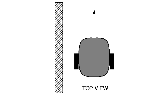
Figure 1: Driving along a Wall Edge
Suppose the robot should be programmed to drive with its left side near a wall, following the wall edge (see Figure 1). Several options exist to accomplish this task:
One solution is to orient the robot exactly parallel to the wall, then drive it straight ahead. However, this simple solution has two problems: if the robot is not initially oriented properly, it will fail. Also, unless the robot were extremely proficient at driving straight, it will eventually veer from its path and drive either into the wall or into the game board.
The common and effective solution is to build a negative feedback loop. With continuous monitoring and correction, a goal state (in this case, maintaining a constant distance from a wall) can be achieved.
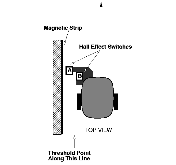
Figure 2: Using Two Hall Effect Sensors to Follow Wall
Several of the sensors provided in the ELEC 201 kit can be used to control the distance between the robot and the wall. For example, two Hall effect sensors could be mounted to the robot as shown in Figure 2. In this example the wall contains a magnetic strip (as is sometimes the case on the ELEC 201 game board). The two magnetic sensors are mounted on the robot as shown. Since the A sensor is closer to the wall, it will trigger first as the robot moves toward the wall, followed by B if the robot continues to move toward the wall. As the robot moves away from the wall, B will release first, followed by A if the robot continues to move away from the wall. A decision process making use of this information is depicted in Table 1.
| A | B | Result |
|---|---|---|
| On | On | too close |
| On | Off | just right |
| Off | On | sensor error |
| Off | Off | too far |
Notice that the situation with A off and B on is indicative of some failure of the sensor or its mounting.
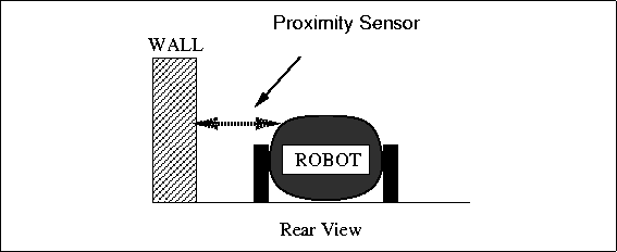
Figure 3: Using a Proximity Sensor to Measure Distance to a Wall
Other sensors provided in the ELEC 201 kit can be used to measure the distance between the robot and the wall (see Figure 3). For example, a magnetic field intensity sensor can be used if the wall contains a magnetic strip. In this case the magnetic field sensor would produce a higher value as the robot got closer to the wall. A light source/photocell pair could also be used. In this case the light source (shielded from stray light, perhaps by a cardboard tube) would be aimed at the wall, and the photocell (also shielded from stray light) would produce a value proportional to the distance from a reflective wall. A "bend" sensor could also be used, although the ELEC 201 kit does not contain any of these useful sensors. In this case, the shorter the distance, the more the bend sensor is bent (see explanation of bend sensors).
Suppose a function were written using the two Hall effect sensors to discern four states: TOO_CLOSE, TOO_FAR, JUST_RIGHT (from the wall), and SENSOR_ERROR. Here is a possible definition of the function, called wall_distance():
int TOO_CLOSE= -1;
int JUST_RIGHT= 0;
int TOO_FAR= 1;
int SENSOR_ERROR= -99;

int wall_distance()
{

    /* get reading on A & B sensors */
    int A_value= digital(A_SENSOR);
    int B_value= digital(B_SENSOR);

    /* assume "ON" means the sensor reads zero */
    if ((A_value == 0) && (B_value == 0)) return TOO_CLOSE;
    if ((A_value == 0) && (B_value == 1)) return JUST_RIGHT;
    if ((A_value == 1) && (B_value == 0)) return SENSOR_ERROR;
    /* if ((A_value == 1) && (B_value == 1)) */ return TOO_FAR;

}
Suppose instead a function were written using a proximity sensor to discern the three states: TOO_CLOSE, TOO_FAR, and JUST_RIGHT. Here is a possible definition of this function, called wall_dist_prox():
int TOO_CLOSE= -1;
int JUST_RIGHT= 0;
int TOO_FAR= 1;
int TOO_CLOSE_THRESHOLD= 50;  /* Embedding threshold constants in this */
int TOO_FAR_THRESHOLD= 150;   /* manner in a real program is not good */
                              /* programming practice.  Instead, they */
                              /* should be placed in a separate file. */

int wall_dist_prox()
{

    /* get reading on proximity sensor */
    int prox_value= analog(PROXIMITY_SENSOR);

    /* assume smaller values mean closer to wall */
    if (prox_value < TOO_CLOSE_THRESHOLD) return TOO_CLOSE;
    if (prox_value > TOO_FAR_THRESHOLD) return TOO_FAR;
    return JUST_RIGHT;

}
Now, a function to drive the robot making use of the wall_distance() function would create the feedback. In this example, the functions veer_away_from_wall(), veer_toward_wall(), and drive_straight() are used to actually move the robot.
void follow_wall()
{
	while (1) {
		int state = wall_distance();

		if (state == TOO_CLOSE) veer_away_from_wall();
		else if (state == TOO_FAR) veer_toward_wall();
		else drive_straight();
	}
}
Even if the function to drive the robot straight were not exact (maybe one of the robot's wheels performs better than the other), this function should still accomplish its goal. Suppose the "drive straigh" routine actually veered a bit toward the wall. Then after driving straight for a bit, the "follow wall" routine would notice that the robot was too close to the wall, and execute the "veer away" function.
The actual performance of this algorithm would be influenced by many things, including:
- How sharply the "veer away" and "veer toward" functions made the robot turn.
- The accuracy of the Hall effect switching thresholds, or how well the proximity sensors measured the distance to the wall.
- For proximity sensors, the settings of the TOO_CLOSE_THRESHOLD and TOO_FAR_THRESHOLD values.
- The rate at which the follow_wall() function made corrections to the robot's path.
Still, use of a negative feedback loop ensures basically stable and robust performance, once the parameters are tuned properly. The type of feedback just described is called negative feedback because the corrections subtract from the error, making it smaller. With positive feedback, corrections add to the error. Such systems tend to be unstable.
Open-Loop Control
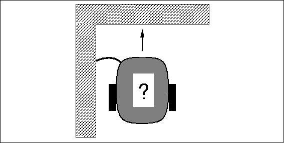
Figure 4: Negotiating a Corner
Suppose now the robot has been following the wall, and a touch sensor indicates that it has reached the far edge. The robot needs to turn clockwise ninety degrees to continue following the edge of the wall (see Figure 4). How should this be accomplished?
One simple method would be to back up a little and execute a turn command that was timed to accomplish a ninety degree rotation. The following code fragment illustrates this idea:
....
robot_backward(); sleep(.25); /* go backward for 1/4 second */
robot_spin_clockwise(); sleep(1.5); /* 1.5 sec = 90 degrees */
....
This method will work reliably only when the robot is very predictable. For example, one cannot assume that a turn command of 1.5 seconds will always produce a rotation of 90 degrees. Many factors affect the performance of a timed turn, including the battery strength, traction on the surface, and friction in the geartrain.
This method of using a timed turn is called open-loop control (as compared to closed-loop control) because there is no feedback from the commanded action about its effect on the state of the system. If the command is tuned properly and the system is very predictable, open-loop commands can work fine, but generally closed-loop control is necessary for good performance.
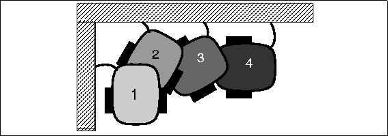
Figure 5: Negotiating a Corner with Touch Sensor Feedback
How could the corner-negotiation action be made into a closed-loop system? One approach is to have the robot make little turns, drive straight ahead, hit the wall, back up, and repeat (see Figure 5), dealing with the corner in a series of little steps.
Feed-Forward Control
There are certain advantages to open-loop control, most notably speed. Clearly a single timed turn would be much faster than a set of small turns, bonks, and back-ups.
One approach when using open-loop control is to use feed-forward control, where the commanded signal is a function of some parameters measured in advance. For the timed turn action, battery strength is probably one of the most significant factors determining the turn's required time. Using feed-forward control, a battery strength measurement would be used to "predict" how much time is needed for the turn. Note that this is still open-loop control — the feedback is not based on the actual result of a movement command — but a computation is made to make the control more accurate.
For this example, the battery strength could be measured or estimated based on usage since the last charge.
Summary
For the types of activities commonly performed by ELEC 201 robots, feedback control proves very useful in:
- Wall following. As discussed in this section.
- Line following. Using one or more reflectance sensors aimed at the surface of the ELEC 201 game board.
- Infrared tracking. Homing in on a source of infrared light, using the IR sensors.
Open-loop control should probably be used sparingly and in time-critical applications. Small segments of open-loop actions interspersed between feedback activities should work well.
Feed-forward techniques can enhance the performance of open-loop control when it is used.