 RUS
RUSAbstract
Introduction
Given the shortage of energy resources, the increase of energy costs, the significant growth and production development and urban infrastructure are the actual problem of energy-efficient transportation technologies and energy consumption. Energy saving in enterprises depends primarily on its effective use in the work of individual industrial systems and processing plants. Such standard systems and facilities of any manufacturing processes are lighting systems, electric motors manufacturing equipment, electric heating equipment, welding equipment, converters, transformers and others. The major consumers of electricity in industry are such inductive receivers as induction motors and transformers. Their work is linked with the consumption of reactive power to generate electromagnetic fields. Reactive power does not produce effective power, but circulating between the receiver and the current source leads to additional loading of transmission lines and generators, and hence reduces the power factor of the network. All this increases the loss of electricity to heat the wire and cable networks, as well as the windings of electrical machines, leading to the need to increase the apparent power generators and transformers in the stations, increasing the voltage loss, increasing the fluctuations of voltage, but also entails the underutilization of the power of prime movers. Reactive power is a factor reducing the quality of electrical power, which leads to such negative phenomena as the increase in payment to the supplier of electricity, the additional losses in the conductors, due to increasing of current, over-capacity transformers and cable sizes, voltage deviation from nominal. The transmission and consumption of reactive power are as well accompanied by a loss of active power.
Relevance of the topic
Reactive power concerns the technical losses in electricity networks.
Unlike the active power, reactive power can be generated not only by generators, but also by compensating devices - capacitors, synchronous condensers or static sources of reactive power that can be installed in substations of electrical networks. Inductive reactive load of electrical appliances, can be counteracted by using capacitive loading, attaching a carefully calculated capacitor. This reduces the reactive power that is consumed from the network and make an adjustment of power factor or reactive power compensation. Reactive power compensation, at present, is an important factor that allows to resolve the issue of energy conservation and reduce the load on the grid.
Scientific Significance
According to estimates of domestic and leading international experts, the share of energy resources in particular, electricity is a significant amount of production costs. This is a quite strong argument to approach with all seriousness the analysis and auditing energy companies and to develop techniques for reactive power compensation.
Reactive power compensation is the solution of the problems of energy conservation.
The inductive reactive load that is created by electrical appliances, can be counteracted by using capacitive loading, attaching a carefully calculated capacitor. This reduces the reactive power that is consumed from the network and is called the power factor adjustment or reactive power compensation.
Reactive power compensation devices
1.1 Capacitors
Capacitors: These are special capacitance that are designed for generation of reactive power. By their action they are equivalent to the overexcited synchronous compensator and can work only as a generator of reactive power. Power capacitors in a single element is 4 - 10 kVAr. Of those elements are The capacitor bank of ythe required power is assembled for these type elements.
Usually, the capacitors is connected to the network of three-phase current in delta. When disconnecting the capacitors its necessary that the stored energy is discharged into them automatically without the participation of staff on duty at the resistance attached to the battery, "tight". Its value should be such that during disconnection a surge will not arise at the clamp of the capacitors.
In comparison with other sources of reactive power sources capacitor capacitors have several advantages:
1) the small active power losses (0.0025 - 0.005 kW / kVAr);
2) ease of use (in the absence of rotating and rubbing parts);
3) ease of manufacturing assembly work (low weight, absence of bases);
4) any dry room can be used in for the installation of capacitors
5) the possibility to choose any needed power compensation;
6) the ability to install and connect at any point of supply;
7) the absence of noise during operation;
8) small maintenance costs.
Among the shortcomings of capacitors, it should be noted the dependence of the generated reactive power on voltage Q = U2·ω·С·10-3 квар; the lack of durability (easily damaged, especially during short-circuits and voltages that are above nominal), the impossibility of continuous adjustment of reactive power, fire risk and the presence of residual charge.
1.2 Synchronous motors
Along with the capacitor banks for reactive power generation should be widely used synchronous motors of different capacities. They transmit reactive power to the network to the consumption site during load on the shaft, allows a wide adjustment range output reactive power, depends less on voltage fluctuations than the cosine capacitors, and improve system stability.
The costs of reactive power by the generators are determined primarily by the cost associated with this additional active power losses.
The amount of reactive power generated by the SM, depends on its load on the active and reactive power and the relative voltage V on its terminals. The highest value of reactive power (Mvar), which can be obtained from the SM, is determined by the formula
![]()
where - the nominal reactive power SM, quartz;
Рн - nominal active power of the SM, kW;
![]() corresponds to the nominal cosф engine;
corresponds to the nominal cosф engine;
![]() - engine efficiency;
- engine efficiency;
![]() - maximum permissible overload SM according to reactive power depends on the engine type, relative to the voltage V at its terminals and the load coefficients of the active power.
- maximum permissible overload SM according to reactive power depends on the engine type, relative to the voltage V at its terminals and the load coefficients of the active power.
The synchronous motors, which are produced by the domestic industry, designed for the leading power factor ![]() and at rated resistive load Рnom and voltage Vnom can produce a nominal reactive power:
and at rated resistive load Рnom and voltage Vnom can produce a nominal reactive power:
![]()
During underload SM for active power ![]() <1 possible overload active power factor
<1 possible overload active power factor![]() > 1.
> 1.
The advantage of SM which is used for reactive power compensation, compared with CB is the possibility of modulating the generated reactive power.
The disadvantage is that the active losses in the generation of reactive power for SMs is bigger than for CBs, as they depend on the square of the generated power SM.
The use of synchronous motors in industrial plants can be useful in the following cases:
1) installation of synchronous motors for actuators instead of asynchronous, where this is possible by technological conditions;
2) installation of more powerful synchronous motors than the required drive mechanism.
The first measure is always advisable. Therefore, in low power factor we must consider as to which mechanisms can be applied to a synchronous motors instead of induction. The suitability of the second measure should be techno-economically feasible by comparison with other options to improve the power factor.
As a rule, in supply systems of industrial CB the reactive power is compensated of the basic (core) part of load and reduce, mainly peaks loads of graphics.
1. 3 Synchronous Compensator
A variety of the SM is the synchronous compensator (SC), which represent the SM of lightweight design with no load on the shaft. Currently, SC with power above 5000 kVAr are produced, they have limited use in the networks of industrial enterprises and only in some cases used to improve the quality of high-power voltage VC with the quick impact load (electric arc furnaces, rolling mills, etc.).
The active power losses in the synchronous compensator capacity of 5000-30000 kVAr during its single load depending on the rated power ranging from 0,02-0,05 kW / kVAr (in slow-moving power up to 500 kVAr - 0,1 ... 0,15 kW / kVAr), ie, make up a significant amount.
The disadvantages of synchronous compensators relate also to more expensive and more complex operation (compared to capacitor banks, for example), the presence of rotating parts, difficult starting conditions and the considerable noise during operation. The positive properties of both synchronous condensers as reactive power sources is the capability of continuous and automatic control value generated reactive power, the independence of the generation of reactive power from the voltage on its bus bars, sufficient thermal and dynamic stability of the windings compensating during short circuits, and the ability to repair damaged synchronous condensers through repairs.
1.4 Generators
While choosing compensating devices, its necessary to determine the feasibility usage proportion of the reactive power of the working generators of the nearest large power plants. The criterion for such a feasibility is the comparison between the cost of generation and transmission of reactive power from the power plants with the costs of plants in the capacitor banks required power. The cost of generation at the same time will be determined only by the cost of additional losses in the generator. In most cases, the transfer of reactive power from generators of the producing substations or located in the immediate vicinity of other local substations is economically feasible if it does not cause or increase the number of cross feed lines, the number of established transformers and other costs to enhance network.
The specific losses of active power of synchronous generator functioning as a compensators without disconnecting the primary engines are 0,15 ... 0,3 kW / kVAr.
Static Thyristor Capacitors
In networks with quick impact load at a voltage of 6-10 kV its recommended to use capacitor banks, and special high-speed reactive power sources (RPS or STC), which must be installed adjacent to the station. The RPS scheme is shown in (Fig. 4). As an adjustable inductance it uses inductance LR and non- adjustable capacitors of C1-C3.
The regulation of the inductance is made by thyristor groups VS, which controls electrodes that are connected to the control scheme. The advantages of static RPS is the lack of moving parts, relatively smooth control of reactive power given by the network, the possibility of three and four-fold overload of reactive power. The disadvantage is the appearance of higher harmonics, which may occur during deep reactive power regulation.
A review of research and development on the subject.
Methods of choosing CD
On the consumer SS, it is advisable to perform it with the capacitor banks connected in parallel load (lateral compensation).
Power CD is defined as:
![]()
where Pф1 - actual maximum of the consumer active power.
If the load graphs for consumer SS are not given, with some margin, we assume that
![]()
where RP and AP – the maximum consumer loads.
The value of tg φэ is set equal to 0.25.
If tg φ1 < tg φэ or Qku <400 kVAr, the CD is not installed.
When choosing the nominal capacity and the number of complete condensing units one should proceed from the necessity of uniform discharge of transformer reactive power. Since the sectional switches on the side of low voltage consumer PC turned off, the number of similar units must be divisible by the number of sections at the substation (two - with double winding transformers and four - with transformer with split windings).
Methods of choosing CD, developed in the Novomoskovsk Institute D.I.Mendeleev.
1. We determines the power CD needed to be installed in SES company
![]()
2. We decide on the feasibility of using SM as a source of reactive power

where k0VN - unit cost of CB, RUB/ kVAr.

where D P (QSM) - loss of SM from the development of reactive power

Substitute values into the objective function
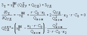
where K1, K2 - reference data; C0 - the cost of the specific power losses; τ - the number of hours of use of the maximum loss.
If Q SM optimal <0, then it is appropriate to compensation only CB.
If Q DM optimal > 0, then all the reactive power is compensated in the SM.
3. determination of the optimal arrangement of the CD on HV and LV.

Making a substitution from the equation constraints and take the partial derivative
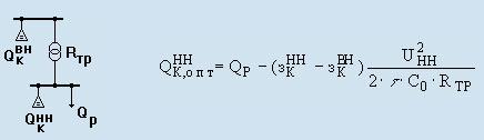
If QHHK optimal <0, then the entire reactive power is compensated by HV
![]()
Conclusion
The originality of this work consists of a comprehensive approach to the problem of reactive power compensation. The technique and program of selecting the optimal use of high-voltage SMs for reactive power compensation and the selection of the locations of the connected capacitor banks in the electricity network of the industrial enterprise of any configuration.
Thus, when considering the level of the value of CD, its installation is economically feasible. Further research is necessary to determine the optimum value of regulatory efficiency ratio, rates of deductions for maintenance of CD and the cost of consumed electricity.
Список литературы
1. Технико-экономическая эффективность систем электроснабжения про-мышленных предприятий / Овчаренко А.С., Рабинович М.Л. - Киев: Техника, 1977. - 172 с.
2. Ильяшов В.Л. Конденсаторные установки промышленных предприятий. - М.: Энергоатомиздат, 1983. - 152 с.
3. Методика розрахунків за перетоки реактивної електроенергії між енергопостачальною організацією і її споживачами. - Київ, 1997. - 36 с.
4. Указания по компенсации реактивной мощности в распределительных сетях. - М: Энергия, 1974. - 72 с.
5. Железко Ю.С. Стратегия снижения потерь мощности и повышения качества электроэнергии в электрических системах // Электричество. - 1992. - № 5. - С. 6-12.
6. Справочник по проектированию электроэнергетических систем / Под ред. С.С. Рокотяна, И.М. Шапиро. - М.: Энергоатомиздат, 1985. - 352 с.
7. Методика начисления платы за перетоки реактивной электроэнергии между электропередающей организацией и ее потребителями. - Введ. Мин. топэнерго Украины, приказ № 19 от 17.01.02.
8. Каталог КУ компании "МАТИК-ЭЛЕКТРО".