


Zhurov Igor'
Faculty: Electrotechnical
Department "Electric drive and automation of industrial-scale plants"
Speciality "Electromechanic systems of automation and electric drive"
Develop methods for controlling the dynamic processes in conditions of uncertainty
Scientific adviser: Dr.Sci.Tech., prof. Tolochko Olga
Abstract on the topic of master's work
Contents
Introduction
1. Sensorless speed detection
1.1. Speed determination of the quantities recorded in the rotating coordinate system
1.2. The speed estimate using state observer
2. Identifying the inertia torque of the electric drive
2.1. Description of the recurrent least squares method
2.2. Development of identity the moment of inertia of the electric
Conclusions
References
Introduction
Relevance of the topic. For quality control of any system we must have a maximum of reliable information about the object of regulation (OR). This task is complicated in cases where the parameters of the object are unknown or changing in the process of his work.
In systems with an asynchronous electric drive there are parametric and signal uncertainties.
To parametric uncertainties include active resistance of stator and rotor, mutual inductance, inertia torque, which has the largest range of changes in the process. To improve the robustness of the control system for changing the inertia torque should be applied self-tuning speed regulator, which requires a parallel on-line identification.
By the signal uncertainties in some cases may include linkage of the rotor and the rotor speed. In connection with this problem in recent years has become a trend of development of methods for sensorless positioning actuator in which the measured value is determined indirectly through readily available measurement of electrical variables.
The scientific significance of the work.
- adaptation of systems of the electric drive to change of their parametres in the course of work;
- design of sensorless control systems of electric drives.
A review of research on the topic in DonNTU exposed that problems of parametric and signal identification are considered in [3, 4, 10].
A review of research on the topic in Ukraine exposed that problems of parametric and signal identification are considered in [2, 5].
A review of research on the topic in the world exposed that problems of parametric and signal identification are considered in [1, 6-9, 11].
1. Sensorless speed detection
Within last decades the tendency of development of sensorless methods definitions of speed at which the measured size is defined by an indirect route through readily available to measurement electric variables, such as pressure on an inverter exit from which the engine, and a current статора eats is observed.
Sensorless speed detection can be performed using various methods, the complexity of which is largely determined by the required range of regulatory requirements and drive to the accuracy of the measurement of speed.
Consider two methods of determining the speed based on forms of mathematical description of asynchronous motors.
1.1. Speed determination of the quantities recorded in the rotating coordinate system
The basis of the principle of construction of the scheme sensorless speed detection laid the mathematical description of blood pressure in the fixed coordinate system  . The equations for the circuits of stator and rotor in such a coordinate system will look like:
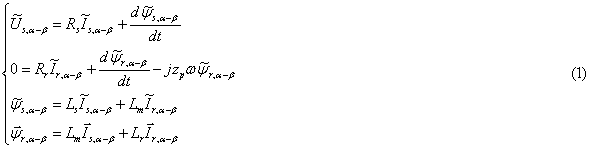
where  ,
,  – the vectors of voltage and current in the stator axes
We must find the value of the  deletion of the formulas of the third and fourth equations of rotor current:

where  – coefficient of the linkage.
Differentiating (2), we obtain:

Define the expression for the second term on the right side of the second equation (1):

Current vector of the rotor can be expressed in terms of vectors flux linkage and stator current on the basis of the third equation (1):

Substituting expression (2), (4) and (5) in the second equation (1), multiplying all sides by Lm, Lr and dividing by grouping terms, we obtain an expression in which, as variables include spatial vectors only those variables that can be measured:

The left side can be written as projections of the stator voltage and current on the axis of the fixed coordinate system:
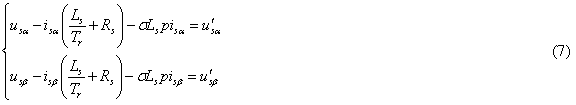
where  ,
,  – intermediate variables, calculated for the circuit shown in Fig. 1.
Then we go to a coordinate system x-y, rotating with synchronous speed. Directing the axis  of the stator flux linkage vector, expression (6) can be represented as:
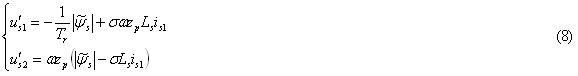
Based on the second of these equations is calculated motor speed[1]

Structure of speed identifier is represented on fig. 1.
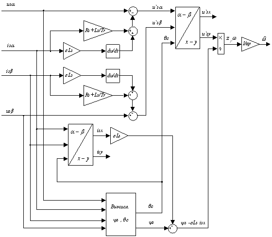 |
Figure 1 – The structure of the speed identifier |
Results of modelling the vector control system with use of the presented identifier are shown on fig. 2.
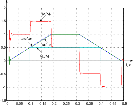 |
Figure 2 – The transients received with using of the speed identifier |
This method of identification of the rate applicable in systems that do not meet high requirements of dynamic parameters of the transition.
1.2. The speed estimate using state observer
One promising alternative methods of recovery speed of the engine to create high-quality vector control systems without using a mechanical sensor on the motor shaft is to use a state observer (SO).
Source for the construction of the SO are the Park-Gorev equations for induction motor in the orthogonal coordinate system, d, q, oriented along the vector of the rotor flux linkage:
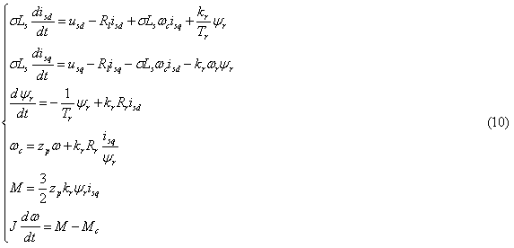
where usd, usq, isd, isq,  – orthogonal vector components of stator voltage and current blood pressure and modulus of the rotor flux linkage; M, Mc – electromagnetic torque and static torque;
  – rotor speed;
  – speed coordinates d, q; Tr=Lr/Rr – electromagnetic rotor time constant; Rs, Rr – active resistance of the windings of phases of stator and rotor; kr=Lm/Lr – complete stator and rotor inductance and mutual inductance.
Structure of the observer is shown in fig. 3. Its input signals are measured coordinates usq, isd, isq and restored by using an identifier [2] and .
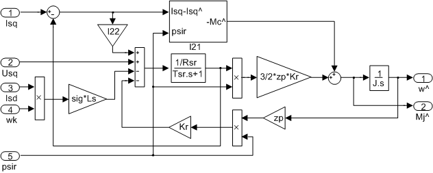 |
Figure 3 – The structure of the state observer |
To provide the desired characteristic polynomial of SO

coefficients correcting links of the SO should be calculated as follows:
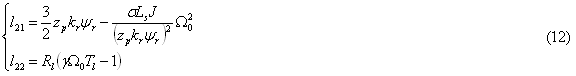
where  – geometric average root (GAR) of the characteristic polynomial.
The transfer function kf(p) of the static moment to the estimation error of speed, as shown in [3] can be identified by the block diagram fig. 4:
– geometric average root (GAR) of the characteristic polynomial.
The transfer function kf(p) of the static moment to the estimation error of speed, as shown in [3] can be identified by the block diagram fig. 4:

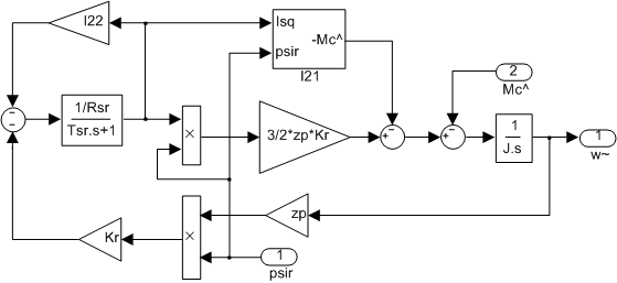 |
Figure 4 – The settlement scheme of SO for an error of estimation of speed |
For steady-state estimation error using (2) will be:

From the expression (3) that, having information on the static moment, the speed estimation error can be compensated. Given the presence of observers, presented in fig. 5, estimates of the dynamic moment, the moment of static resistance can be identified by the following formula:

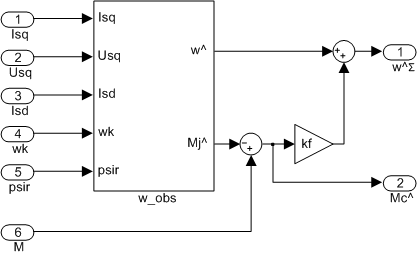 |
Figure 5 – The structure of SO with indemnification of an error of estimation of speed and calculation of the load torque |
If in the SO transfer coefficient kf replace the transfer function kf(p), then compensation will be carried out not only in the static but also in dynamics.
On fig. 6 are shown transients in vector control system at use for speed estimation the state observer.
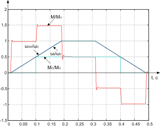 |
Figure 6 – The transients received using the state observer |
2. Identifying the inertia torque of the electric drive
Approaches for determining the parameters can be divided into two groups: recurrent and analytical. Number of tasks that can be solved analytically, is limited by the need to make significant assumptions about the studied system models [5]. Recursive methods are a basic approach to identifying the parameters of the object control (OC) using adaptive (adjustment) models [6-9]. Block diagram of system parameters identification using adaptive model shown in fig. 7.
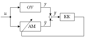 |
Figure 7 – The structure of parameter identification system on the basis of adaptive model |
One of the most common methods of parameter identification, allowing enough to accurately estimate the parameters of the object is a recursive least squares method (RLSM).
2.1. Description of the recurrent least squares method
Suppose that a linear analog OC with one entrance and one exit with some degree of accuracy can be described by a discrete transfer function (TF):

TF (16) corresponds to the difference equation:

where y(z), u(z) – z-transform of output and input signals, respectively; y[k], y[k-1], ..., y[k-n], u[k], u[k-1], ..., u[k-m] – a sequence of values of output and input, respectively, at fixed times; k – an integer that corresponds to a specific point in time; n, m – the order of the denominator and numerator, respectively.
Uniting the coefficients of equation (17) in the parameter vector:

and the values of the output and input signals at discrete points in time – a vector of measured signals:

Then equation (17) becomes:

Adaptive model output can be calculated as:

where  – evaluation of output and the vector of unknown parameters at the appropriate time.
At use RLSM the integrated square-law error of estimation is minimised. Thus expression for parameter estimations minimizing ISE looks like:

Vector correction to the k-th step is determined by the expression:

2.2. Development of identity the moment of inertia of the electric
We apply the above methodology to identify the moment of inertia of the actuator. In this case, as the OS is convenient to apply the mechanical part of the electric drive with a continuous TF:

At digitization TF (24) of Tastin’s method and some transformations [9-11] we will receive following equation which is initial for construction of adaptive model:

Comparing (25) with (23), we will designate:
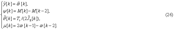
In view of (23) and (26) (22) becomes:

Identified parameter is formed from the parameters of the adaptive model according to the equation:

The structure of of the motor drive inertia identifier is shown on fig. 8.
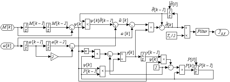 |
Figure 8 – Structure of the motor drive inertia identifier |
 |
Figure 9 – Visualisation of transients in AM vector control with inertia identification consists of 7 shots with a delay between shots 1 sec, delay before repeated reproduction is 2 sec; number of repetitions is 5) |
Conclusions
- Developed in the SO it is possible to apply to construction of astatic systems on indignation of indirect speed regulation of asynchronus machine with vector control without installation of mechanical gauges on an engine shaft.
- By means of developed in the SO it is possible to restore precisely value of rotor speed at the expense of indemnification of an error of estimation arising in the presence of revolting influence in object.
- The developed identifier allows to estimate precisely enough the inertia torque of the electric drive under condition of presence of known signals of speed of rotation of the engine and the electromagnetic moment.
- At a constant of the electromagnetic moment identification process stops;
- In cases when there are intervals of time with a constant of the torque, it is necessary to apply a test signal (a sinusoid, a saw or a meander) with small amplitude and high frequency.
- PWM positively influences identification process, allowing to refuse introduction of a test signal;
- The factor influences speed of identification;
- For achievement of satisfactory quality of identification the identifier's samle-time should be equal or less in an integer of times of current controller's samle-time.
References
- Соколовский Г.Г. Электроприводы переменного тока с частотным регулированием: Учебник для студ. высш. учебн. заведений / Г.Г. Соколовский. – 2-е изд., стер. – М.: Издательский центр «Академия», 2006. – 272 с.
- Пивняк Г.Г., Волков А.В. Современные частотно-регулируемые асинхронные электроприводы с широтно-импульсной модуляцией: Монография. – Днепропетровск: Национальный горный университет, 2006. – 470 с.
- Толочко О.І. Аналіз та синтез електромеханічних систем зі спостерігачами стану. Навч. посібник для студентів вищих навчальних закладів. – Донецьк: Норд-Прес, 2004. – 298 с.
- Толочко О.И. Астатическая по нагрузке система управления скоростью асинхронного двигателя с наблюдателем состояния./ Толочко О.И., Чекавский Г.С., Песковатская О.В.// Сборник материалов V Международной (XVI Всероссийской) научной конференции по автоматизированному электроприводу "АЭП-2007": 18 -21 сентября 2007 г. - Санкт-Петербург, 2007. - С. 69 - 71.
- Балахонцев О.В. Ідентифікація параметрів і координат асинхронного електропривода в режимі реального часу. Дисертація на здобуття наукового ступеню канд. техн. наук: 05.09.03 / НГУ. – Дніпропетровськ, 2006. – 167 с.
- L. Ljung System Identification – Theory For the User, 2nd ed / L. Ljung. – N.J.: PTR Prentice Hall, Upper Saddle River, 1999. – 609 p.
- Семенов А. Д., Артамонов Д. В., Брюхачев А.В. Идентификация объектов управления (учебное пособие) / Семенов А. Д., Артамонов Д.В., Брюхачев А.В. - Пенза: Изд-во Пенз. гос. ун-та, 2003.- 211 с.
- Изерман Р. Цифровые системы управления / Изерман Р. – М.: Мир, 1984. – 541 с.
- Inertia identification and auto-tuning of induction motor using MRAS / Yujie Guo, Lipei Huang, Yang Qiu, Masaharu Muramatsu // Power Electronics and Motion Control Conference. Proceedings. IPEMC 2000. The Third International (15-18/08/2000) vol. 2. – 2000. – pp. 1006-1011.
- Трандафілов В.М. Особливості градієнтного метода ідентифікації моменту інерції електроприводу / В.М. Трандафілов, О.І. Толочко, В.В. Божко // Автоматизація технологічних об’єктів та процесів. Пошук молодих. Збірник наукових праць X Міжнародної науково-технічної конференції аспірантів та студентів в м. Донецьку 18-20 травня 2010 р. – Донецьк: ДонНТУ, 2010. – С. 260-262.
- Andreescu G. D. Torque-speed adaptive observer and inertia identification without current transducers for control of electric drives / Andreescu G. D., Rabinovici R. // International conference on electrical machines, Espoo, FINLANDE (28/08/2000). 2000. – P. 1428-1432.