 |


|
||||||||||||||||||||||
|
Faculty of ecology and chemical technology Department of chemical technology of fuel Speciality "Chemical technology of fuel and carbon materials" Study dispensing device for chamber plant of dry coke quenching on a physical model Scientific adviser: t.s.с., docent Evgeniy Zbikovskiy |
|||||||||||||||||||||||
|
|
Author's abstractContentsThe chamber design PDCQ, which suggested by the Department of CTF DonNTU EntryDry coke quenching is an effective energy-saving and environmental technology, since significantly improves the energy efficiency of the coking plant at the same time a significant improvement of coke quality and reduced emissions compared to wet quenching [1]. Plant of dry coke quenching (PDCQ) Giprokoks design, received the overwhelming spread of the world. However, the widespread introduction of PDCQ Giprokoks is hampered by a number of significant drawbacks: significant capital costs, loss of coke ("Chad") as a result of interaction with the oxidizing components of the circulating gas, high costs of electricity on the circulation of gases, air pollution of excess of circulating gas and dust, etc. To a large extent these deficiencies are caused by low-intensity heat transfer between the coke and gases in industrial chambers [2 – 3]. The main reason for reducing the intensity of heat transfer in industrial chambers of dry quenching is the uneven distribution of coke and gas flows in cross section. The chamber design PDCQ, which suggested by the Department of CTF DonNTUDry quenching of coke is an effective energy-saving technology, which provides recycling to 35% of the heat that is spent on coking coal, and that improves the environment at coke plants. However, the wide application of this process prevents the awkwardness of dry quenching of coke and the high cost of electricity to circulate the inert gases. To a large extent these deficiencies are caused by low-intensity heat transfer between the coke and gases in industrial chambers. For practical data stay in the coke industry chambers Giprokoks is 2 – 2,2 hours, whereas the cooling time of it from 1000 to 200 – 220°C, calculated on the values of heat transfer coefficients in the experimental conditions, does not exceed 1,0 – 1,5 h [5]. Developed-compliant design. The chamber dry coke (Fig. 1) has case 1 divided by 2 and forchamber extinguishing chamber 3, placed at the bottom of the chamber of quench flow divider of coke, made in the form of Λ-shaped beams 4, installed in parallel with the step equal to the width of the foundation beams (700– 900 mm). The inner surface of the Λ-shaped beam 4 forms distribution channels 6, connected holes 7 in the case 1 with the peripheral distribution channels 8 for supplying up the cooling gas. Channels 10 are connected passages 9 in the housing with the peripheral channel 12 teams for the diversion of cooling gas. The chamber has a dry coke loading and unloading device 13 and 14, respectively. 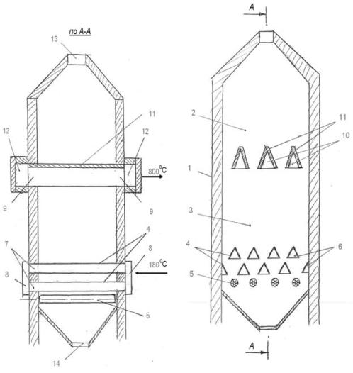 Research of input and output of refrigerant gas in the velocity distribution in the chamber model DCQ of design department CTFThe experimental procedure was as follows. On the distribution grids at intervals of 70 mm were placed 6 plates. Plates, which are adjacent to the lateral walls of the chamber had a width of 35 mm, others– 70 mm. Thus the simulated launch conditions when applying the cooling gas distribution beams. Next to the chamber was poured coke. In the layer of coke in the section to determine the velocity distribution, along the length of the chamber 3 devices for measuring pressure are installed. After reaching a height of 500 mm backfill coke coke surface is flatten, are three plates of width 75 mm distributed to simulate the conditions of diversion refrigerant gas from the chamber. After the experiment, Coke was unloaded from the chamber and a device for measuring the pressure mounted again: in other locations or the same to test the reproducibility of previous experience. To exclude the effect of wall porosity on the velocity distribution of the cross section of the apparatus it is necessary to satisfy the relations [6, p. 120]:
where D– diameter of the device; d– particle diameter. In our case the diameter of the product one should take the smallest horizontal dimension of installation– a width of 150 mm. This size is slightly higher than the minimum allowable, determined by the ratio (1). Therefore, from the feed of material, were all the large pieces selected, thus ensuring the observance of (1). The presence of the influence of wall porosity was controlled by the velocity distribution at the exit from the layer of coke. The results were processed in accordance with the requirements of similarity theory in the form of the dependence of the dimensionless velocity on the dimensionless coordinate X [7]:
where wi – velocity of gas in the pilot point; wmax – he maximum velocity of the gas in this section; xi – the distance from the edge of the experimental setup to the point; L length of the installation. Diagram of velocities in each section was based on measurements of not less than 3 points [8]. For individual sections of the measurement of velocities were carried out in 6 points. Upon the experiment was builg 8 diagrams for different sections. Based on diagram of velocities the location and size of the stagnant relative to the circulating gas zones in PDCQ proposed design was determined (Fig. 2). The total volume of badly blown zones is 8.6% of the total quenching chamber, the total volume of zones with reduced speed of the cooling gas 6.0%, significantly better than the exploited industrial plants [3]. Figure (3) represented the velocity of the refrigerant gas in the chamber PDCQ proposed design. Of course, these data are based on the results of experiments with the cold model are indicative only. However, they show the effectiveness of the proposed design and the need for further research. The results are a sufficient basis for the construction of a pilot plant. 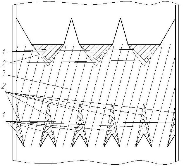 Figure 2– Location of dead zones in PDCQ proposed design. ConclusionsDue to the shortage of energy resources in Ukraine, development and exploration of equipment of dry coke is of particular importance and relevance. The widespread introduction of this process in the coke production plant will reduce the cost of natural gas and other energy sources in the industry, to significantly improve the ecological situation in industrial centers and working conditions in the coke making, to reduce losses from corrosion of equipment, greatly improving the quality of coke [9]. However, operating at coke factory plants dry coke (PDCQ) have significant design flaws that reduce the effectiveness of using sensible heat of coke and reliability, require significant expenditure on repairs and maintenance. Therefore, in many countries at present is actively working to improve the technique and technology of dry coke quenching, reducing capital and operational costs, increase the stability of PDCQ [10]. Measurement scheme was designed to investigate the convective heat transfer of coarse materials. It was conducted: the study of uniformity of flow distribution of coke and gas with dispensing devices for the entire cross section quenching chamber, the definition of gas velocities at different points in the apparatus, the construction of plots of the velocity distribution and the definition of dead zones within the studied section. In this study it was found that in PDCQ, proposed Department of CTF, in 95.5% of the observed mode of the gas close to ideal displacement. That is, the installation is efficient and there is construction of a pilot plant. 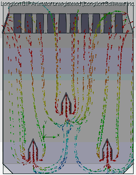
Figure 3– Velocity of the gases in the PDCQ (animation, 96,6Kb, 5 images, duration: 5 repetitions) References
|
||||||||||||||||||||||