
Aim and objectives of research
A brief review of the existing braking devices
A review of research and development on this theme
The primary means of protection and management of mine winders are the brakes, design excellence which largely determines the reliability and security of the entire hoisting plant. Analysis of failures of lifting machinery in the mines shows that most of them is precisely because of faults or imperfections brakes are not identified and eliminated in a timely manner[9].
In modern mining enterprises entire volume of extracting the minerals is usually issued one barrel. Now operated by the powerful lifting systems, capable of lifting loads of 50 tons at a speed of 16 m/sec.
Existing braking systems in some cases have not been able to provide range safety braking deceleration values within the limits of standardized safety rules[8].
One of the most effective ways to solve the problem is a multimodal axial disc brakes, instead of the traditional radial pressing of brake pads to the rim[4].
The purpose of master's thesis is to study the dynamics of transient processes occurring in the lift installation in the fuse brake disc brakes.
Research problems are the following:
— to prove that powerful mnogokanatnye lifting equipment shall be equipped with multi-modular axial disc braking system;
— develop a mathematical model of the dynamic state of the lift installation.
There are two types of braking devices.
1. Radial brake application effort.
2. With an axial braking force application.
The most common today are the first brake device with a radial attachment braking. They are divided into:
— brakes with the angular displacement of blocks (picture 3);
— brakes with the translational movement of blocks (picture 4);
— combined[3].
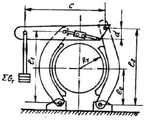
Picture 3 — Kinematic diagram of the brake winding machines with the angular displacement of blocks
Picture 4 — Kinematic diagram of the brake hoists with forward movement of pads
For high-lifting machines, including mnogokanatnyh, use a third type of brakes. In the design plan of all the braking devices consist of an executive body, the brake actuator and administration.
The Executive Body consists of a brake brake beams, brake shoes with friction linings, brake rim, and lever-hinge mechanism. According to the principle of inhibition executive bodies brakes are divided into two main types:
— radial type (picture 1 а, 1 б), in which two diametrically located hard brake pads 3, equipped with friction pads 2, pressed both sides to a cylindrical rim of the brake drum 1 with a force F, directed along the radius of the drum;
— axial type (picture 1 в),in which two brake pads 3, constituting a so-called braking unit, pressed both sides to the alignment with a drum brake disc 2 (on a single disk can mix up to eight or more modules) with a force F, directed along the axis of the drum.
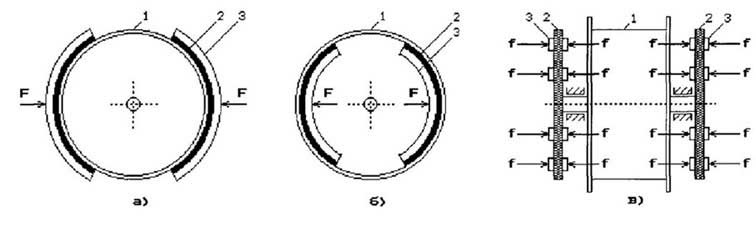
Picture 1 — Sketches of the executive body of the brake of the radial (a, b) and axial (c) type
Brake actuators lifting machines, depending on the source of the braking force divided by cargo, freight, hydraulic, spring-hydraulic, spring-pneumatic (bezgruzovye and cargo), cargo-pneumatic braking device with spring-hydraulic disc brakes. For any type of brake gear brake force provided by the pre-compressed springs or weights brake loads - it's the basic rule of brake systems: the lift must be inhibited to be independent of the operator forces.
Control apparatus braking devices winders are designed to provide the desired mode for operating and safety brake. These include electro-pneumatic and electro-pressure regulators, various types of valves control, air diffusers, locking and loading, pressure, safety valves, check valves, valves, slow braking, solenoid valves, adjustable exhaust apparatus, electro-pneumatic valves and others.
For decades, the design of these machines were improved and modified, together with technological progress, the total number of species and the purpose is very large, a description of their construction and operating principle are described in detail [5, 6, 7] and others.
Of the variety of devices control braking systems can provide three-way valve and pressure regulator.
The most important parameters of the braking device is idle time and reaction time the brakes. The duration of idling safety brake operating hoists in accordance with the requirements of safety regulations [8] must not exceed:
0,5 с — for cargo-pneumatic and pneumatic spring-load actuators;
0,6 с — for cargo-hydraulic actuator;
0,3 с — with spring-pneumatic and spring-hydraulic drive, as well as for all newly created structures brakes.
A response time of brake safety rules limited «over» value 0,8 sec. With regard to the braking device of the radial type, these two parameters is not always achieved in accordance to safety regulations, it is the main drawback of such devices. Therefore, the appropriate application of brakes of the axial type, since their time idling brake is less than 0.2 sec., And the reaction time the brakes are not more than 0,25 sec.
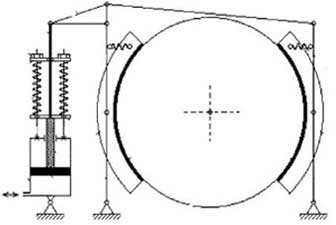
Propose the use of modern brakes axial type (disc brakes), general form of which is shown in picture 2.
Brake discs are rigidly connected to the drum and, most often, their functions are performed directly flange of the drum. Brake modules are installed in special pedestals («pedestals») (picture 2), rigidly connected with the foundation of the machine. Working «body» modules, as rule, are compressed air or liquid (technical oil pressure).
In order to improve the safety and reliability of the braking devices of any type should be placed on both sides of lobovin drum brakes have independent drives (in multi-modular disc brakes are independent, each module separately, that is their competitive advantage).
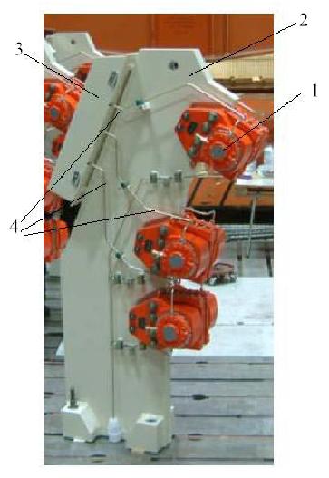
Picture 2 — Brake disc: 1 — braking element, 2 — pedestal, 3 — control valve, 4 — pipelines.
Development of design and definition of rational parameters of disc brakes engaged Belobrov, Stepanov, Traube.
We define the dynamic processes at work hoisting plant in operation and emergency operation.
For this loan output differential equations, dynamical states shown in Picture 6 a mechanical system of five discrete bodies (two vessels, two hoisting pulley machine with a reduced mass of the gearbox and rotor), interconnected by elastic inertial (with distributed masses) bonds — ropes, based on studies professor Dvornikov and his students[1,2].
To build further mathematical model of the dynamic state of the lift installation will take the following basic simplifying working hypotheses and concepts on which it is based.
1. All headaches are considered vehicles nekrutyaschimisya ropes. Taken into account only their longitudinal movement along its own longitudinal axes, including the inclined strings of rope. The rope is considered as one-dimensional object with a mass distribution, the longitudinal stiffness and dissipation characteristics.
2. Mass of branches balancing ropes given to the respective masses of lifting vessels, performing one-dimensional motion in the direction of axes attached to his head-rope. For systems with a lifting machine drum, which in most cases operated without counterbalancing ropes, it is not a simplifying assumption, but a statement of well-known fact.
3. Drum machine (or two drums), motor rotor, rotating gears and wheel gear (if any) are treated as a single structureless rotating mass, called the weight lifting machine.
4. Hoisting pulley of each branch is also considered as a single structureless rotating mass that interacts with the slanted without slipping a string and plumb the appropriate branch of the rope.
5. It is assumed that the moments of friction in the bearing assemblies of pulleys and drum machines, as well as friction in the guide devices are no blood vessels. Accounting inevitably occur "harmful" resistance is within the concept of the Rayleigh hypothesis, the internal friction.
Schematic schematization of the physical model is depicted in picture 6, which shows the lift vessels, located in one of their original positions when laden vessel (blackened rectangle) only begins to rise up, and empty (white box) - to descend. Dotted lines show the vessels in the final lifting operation left the vessel.
In this figure, the following symbols and terminology: Мпр — moment of the drive given to the main shaft of machine; m1, m2 — laden mass lifted (first) and lowered the empty (second) vessel; m3, m4 — masses of the corresponding hoisting pulley; m5 — weight of the car to take the weight reducer and electric motor rotor; α — angles to the horizontal string ropes; l1,l2,...l8 — so-called markers or longalnye longalnye coordinate measured from the initial position in the trunk of the rising (left) of the vessel.
In this case, l1 and l2 denote the coordinates of the accession of the head rope to the first and second vessel, l3 and l4 means the point of crowding the head rope and pulley to the first point of escaping from the second pulley, l5 and l4 mean point of escaping from the first rope pulley and the point of crowding on the second Pulley, l7 and l8 means the point of crowding the rope on the drum machine and point escaping from the drum.
Obviously, in the fixed frame of reference longalnye coordinates l1, l2 are variable in time, а l3, l4, l5, l6, l7, l8 — constant because of the constructive elements of the lifting arrangement of the complex.
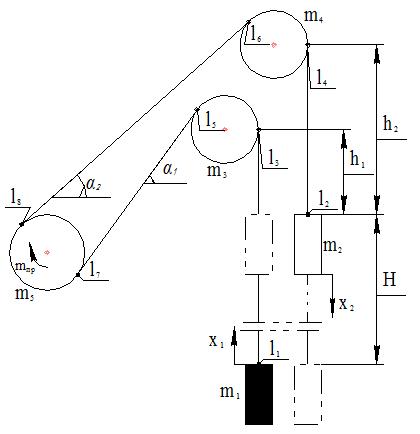
Picture 6 — Schematization setup and coordinate system
Picture 7 — Schematization installation
(animation, volume — 65,1 Кб, consists of 23 frames, 7 repeats, made in mp_gif_animator)
In connection with the introduction of longalnyh marks, longalnaya Euler coordinate s, marking the position of an arbitrary point of the head rope, will vary from s = l1 up on the first plumb up to s = l3, then from s = l5 down and left on the first string to s = l7 , Then from s = l8 up and right on the second string to s = l6, finally, from s = l4 down on the second plumb to s = l2. Therefore, s ∈ [l1, l2], and then
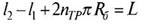 (1)
(1)is the total length of the hitch in the two head-ropes (nтр — number of turns of friction at the drum flange, Rб — radius of the drum), remain, of course, constant for any position of vessels in the trunk. In view of the small diameter pulleys and the drum as compared with the lengths of strings and a plumb head rope is permissible to take l3 = l5, l4 =l6, l7 =l8.
And since the difference
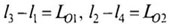 (2)
(2)are the lengths of the first and second branches of the plumb line of head rope, which vary in time, but the difference
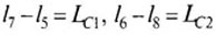 (3)
(3)are unchanging over time the length of the first and second strings, then the estimateL = LO1+ LO2+ LC1+ LC2. Difference l3 - l1 and l2 - l4, representing, in accordance with (2) the length of the branches of a plumb line ropes, are algebraically related to each other, since by Picture 6 (l3 - l1 ) + (l2 - l4 ) = LO1 + LO2 = h1 + h2 + H, where h1 — the minimum length of the first rope plumb position during the first vessel to be unloaded, h2 — the smallest length of the second rope with a plumb-line position of the second vessel to be unloaded, Н — height of lift. Thus, the length of the plumb line LO1 and LO2 uniquely determine the so-called quasidynamic position of vessels in the trunk (the true dynamic situation of blood vessels is determined by the coordinates x1 and x2, which will be discussed below). In this connection it is possible to express these lengths by the dimensionless coordinate ξ:
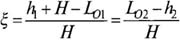 (4)
(4)This shows that in the initial position of vessels when LO1 = h1+H and LO2 = h2 (rising vessel at the bottom) coordinate ξ = 0, and in the final position when LO1 = h1 and LO2 = h2+ H (rising vessel is at the top) coordinate ξ = 1. Thus, the domain of the dimensionless coordinate ξ is a closed interval [0,1], and in this regard with the help of (4) and (2) write
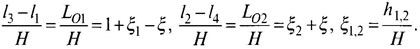 (5)
(5)Coordinate of the first vessel x1 will count down from its initial position at the bottom of the barrel (in boot) and the coordinates of the second vessel x2 — from its initial position at the top of the trunk (in the discharge), as shown in picture 6. These coordinates is determined by the current dynamic situation of blood vessels in the trunk.
Angular displacement of rotating elements (machines and pulleys) to give a linear relationship by:
 (6)
(6)where φ3,4, φ5 — angles of the pulleys and the drum, measured from some of their initial position, which, in combination with linear displacements x1 and x2 are two vessels form a system of generalized coordinates of discrete bodies in the considered mechanical system undergoing a one-dimensional motion in accordance with the working hypothesis 1.
Mass of blood vessels m1 and m2 in accordance with the working hypothesis 2 and substituting the relations (5) by the formulas:
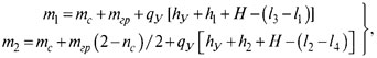 (7)
(7)where mс — mass of the empty vessel, mгр — mass of payload (assuming that the first vessel — laden), nс — number of vessels in this setup (nс = 1 for odnoskipovyh or odnokletevyh, and nc = 2 dvuhskipovyh or dvuhkletevyh lifts), qу and hу — respectively, the linear mass and the smallest length of rope plumb line balancing. In the absence of a system of balancing the rope enough to put in (7) qу = 0.
The masses of the pulleys (m3, m4) and machinery (m5) with the corresponding moments of inertia and mass associated segments of ropes, pulleys and drum envelopes, by the formulas
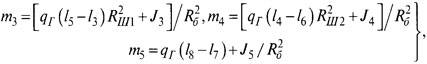 (8)
(8)where qг — the total mass of the linear head-ropes, Rш1 and Rш2 — the radii of the first and second pulleys.
Total weight of the lift installation, including a discrete mass mk (k = 1,2 ,..., 5), calculated by formulas (7) and (8), and includes a total mass distribution plumb and string ropes, called reduced to a circle of winding ropes mass of moving parts lift installation or just the total mass, which, using relations (1) and (2) is defined by:
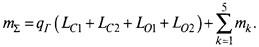
The motion of the bodies constituting the circuit in picture 6, is subject to the action on these external forces of different nature. First of all, to lift the vessels moving in a vertical shaft, of course, the forces of gravity, and in accordance with the working hypothesis 5 and the definitions (7) can be written:
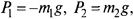 (9)
(9)where g — acceleration of gravity, these forces in accordance with the definitions (7) is variable, if qу ≠ 0, and do not depend on the position of vessels in the trunk, if qу = 0.
By the same hypothesis 5, the external forces acting on the hoisting pulley, is identically equal to zero. Thus, in addition to (9) we write
 (10)
(10)On the drum machine in normal operating modes of movement operates a driving moment Мпр = iред*Мэ actuator, where iред — transmission ratio gearbox, and in modes of operating and safety braking it is exposed to a braking torque, M, and these two points, not only can not act simultaneously, but also between the moment of disconnection of electric toe and the onset of the inhibition tnt a time interval, called the idle time in during which the drum is virtually free from external forces. Therefore, symbolically take
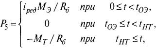 (11)
(11)and it is expected, as actually happens in practice that by the time toe the whole system in a state of quasi-static equilibrium.
Braking torque Мт is variable in time and is subject to well-known relation:

where Mmax = Fрас*Dб/2; Tт — time constant of the brake.
As for the electric driving moment Мэ в (11), it must be regarded as a functional, defined by Kloss. Symbols adopted here can fully apply to systems mnogokanatnogo rise to the location of the machine in the tower copra, dynamic state which can formally describe, if we put m3 = m4 = 0 (in the absence of deflecting pulleys) or take one of the equalities m3 = m4 = 0 or 0, depending on which side are deflecting pulleys[3].
In this paper, was based on studies of the dynamics of transient processes occurring in the lift installation in the fuse brake disc braking systems, it was proved that a powerful lifting equipment shall be equipped with multi-modular disc brakes. Were also derived differential equations of the dynamic state of the lift installation, for use in the future when developing a mathematical model of the dynamic state of the lift installation.
1. Дворников В.И., Къерцелин P.E. Теоретические основы динамики шахтного подъемного комплекса. — София, МОНТ, 1992. — 363 с.
2. Дворников В.И., Теория и моделирование динамического состояния шахтного подъемного комплекса. Дис... докт. техн. наук. — Донецк, 1989. — 385 с.
3. Шахтный подъем: научно-производственное издание\Бежок В.Р., Дворников В.И., Манец И.Г., Пристром В.А,; общ. Ред. Б.А. Грядущий, В.А. Корсун. — Донецк: ООО «Юго-Восток, Лтд», 2007.-624 ил., 233 библтогр.
4. Трибухин Валерий Анатольевич. Обоснование параметров систем торможения многоканатных подъемных машин с многомодульным дисковым тормозом : Дис... канд. техн. наук: 05.05.06 / НИИ горной механики им. М.М.Федорова (НИИГМ им. М.М.Федорова). — Донецк, 2003. — 165л. : рис. — Библиогр.: л. 152-160.
5. Руководство по ревизии, наладке и испытанию шахтных подъемных установок. Изд. 2-е, переработанное и дополненное / Бежок В.Р., Чайка Б.Н., Кузьменко Н.Ф. и др. — М.: Недра, 1982.- 391 с.
6. Неисправности шахтных подъемных установок. Изд. 2-е переработанное и дополненное / Бежок В.Р., Грузутин Р.Я., Калинин В.Г. и др.— М.: Недра, 1991. — 368 с.
7. Димашко А.Д., Гершиков И.Я., Кревневич А.А. Шахтные электрические лебедки и подъемные машины: Справочник. — М.: Недра, 1974. — 363 с.
8. НПАОП 10.0 — 1.01 — 05. Правила безопасности в угольных шахтах. — К.: Відлуння, 2005.- 398 с.
9. Найденко И.С. Ревизия, наладка и испытание тормозных устройств шахтных подъемных машин. — ГОСГОРТЕХИЗДАТ, 1960. — 295 с.
10. ВЫБОР И ОБОСНОВАНИЕ ПАРАМЕТРОВ ДИСКОВОГО ТОРМОЗНОГО УСТРОЙСТВА ШАХТНОЙ ПОДЪЕМНОЙ МАШИНЫ Н.А. Скляров, канд. техн. наук, проф., ДонНТУ [электронный ресурс]. - Mode of access: http://www.nbuv.gov.ua/.../St18_19.pdf