RUS | UKR || Master's portal of DonNTU

Kiseleva Irina

Kiseleva Irina

Faculty: Mining-geological
Speciality “Technology and engineering of investigation of deposits of minerals”

Development of hydraulic mechanism with high single blow energy

Scientific adviser: Vladislav Rusanov


About author


Summary of research and developments

Сontent

Introduction

      The purpose of research is the development of hydraulic double action mechanism with high single blow energy.
      Tasks:
      – Development of design hydraulic mechanism for the elimination of stuck pipe in the borehole;
      – Carrying out theoretical studies of the working cycle of hydraulic mechanism.
      The subject of research is the design of existing hammers.
      The object of research — modern technical means for the elimination of sticking the drill.

1. Research relevance

      Construction of wells – time–consuming engineering process, often complicated by various types of crashes that reduce productivity and increase the cost of drilling. To eliminate accidents, is spent from 5 to 10% of the time in a year. Often the reasons for cancellation of wells that have not fulfilled the geological settings are accidents and complications.
      One of the most widespread, diverse, complex and labor–intensive types of accidents in the exploration drilling are clamps. They account for 60 – 80% of emergency time. Besides, the cliffs, deployment and drop tool clamps are often accompanied or preceded it. With increasing of exploration drilling depth and reducing of diameter wells complexity and severity of sticking, as well as the process of their elimination are continuously increasing. And if the elimination costs of one break per year are reducing, then the elimination of one stuck – is increasing. The costs of auxiliary operations directed to preventing and eliminating of stickings are greatly increased, as well as complications that precede it.
      Development and implement of effective methods and technical means of preventing and eliminating of stickings are one of the important technical problems of drilling wells.
      One of the effective ways of sticking elimination is the use of a shock device – hydraulic vibrator.

2. Summary of results

      Currently numerous constructions of hydraulic vibrators are developed, that are used for sticking elimination. One of the most promising constructions is of the hydraulic vibrator one, it is of a dual action with a differential piston and double-valve distribution of hydraulic fluid developed at the department of "Technology and Technology Exploration" of Donetsk National Technical University.
      However, its use in the practice of drilling showed a definite decrease in the efficiency of the hammer hitting the anvil and the efficiency of the device in general. This defect is due to the fact that the piston striker, picking up maximum speed on the section of the working stroke, loses some of it during interchange of the valve group with the help of hydraulic braking. Thus, the rate of hammer collision with the anvil will be less than the maximum achieved in the process of movement of the piston, which reduces the efficiency of the device and the effectiveness of its work.
      To eliminate these shortcomings, the following design of hydraulic vibrohammer is presented.

3. Description of the developed mechanism

Device structure


Рiс. 1 – The scheme of hydraulic hammer

      The composition of the hydraulic vibrohammer includes a body 1 with control adapter 2, the upper 3 and lower 4 anvils. To the terminal adapter 2 is mounted valve box 5 with the cylinder 6, where a piston 7 is placed, equipped with a shank 8, installed in the chamber 9, made in the body of the striker 10. The valve group is represented by an inlet 11 and outlet 12 valves, sleeve 13 and spring 14.
      Shank 8 of the piston 7 is provided with a lock 15 for the interaction of the extreme positions of recesses 16 and 17, made in the chamber 9. The distance from the upper end of shank 8 and the upper inner face of the striker 10 is equal to the free movement of the piston 7.
      The lower anvil is provided with four channels 18, connecting the space under the striker 10 with the environment.

The device works as follows:


Рiс. 2 – Hydraulic hammer to eliminate sticking

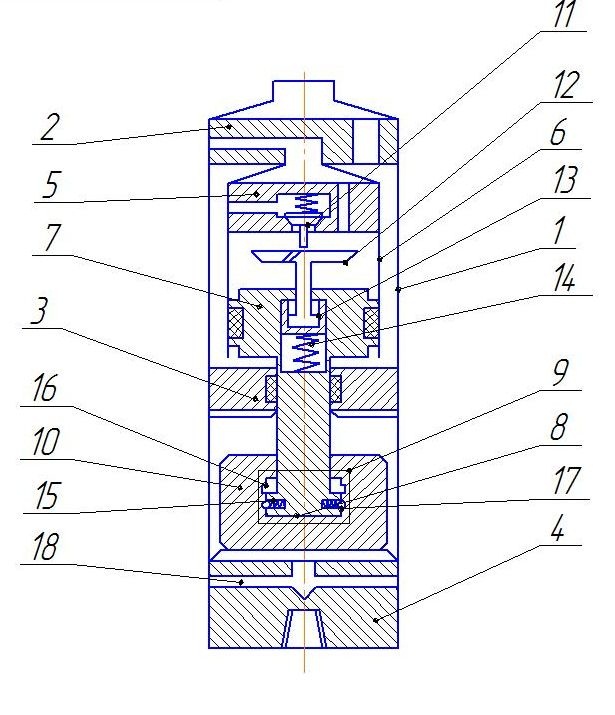
      Vibrohammer of the lower anvil is connected to the stuck tool. Initially, the piston 7 and the firing pin 10 are in the lowest position, with the latches 15 are placed in the groove 17, locking the piston 7 with respect to the striker 10. Intake valve 11 is closed and the outlet 12 is open. When a working fluid in hydraulic vibrohammer , it enters the channel in the switch adapter 2, the annular gap between the housing 1 and the cylinder 6 with piston 7, moving the latter up. The liquid from the piston cylinder cavity 6 is displaced into the well through the channels in the valve box 5 and the switching adapter 2. Valve group is in position by fluid pressure on the inlet valve 11. Therefore, when lifting piston 7, a compression valve spring 14 takes place. After passing through the working stroke when the piston 7 attains maximum speed, it strikes at the intake valve 12. Simultaneously, the firing pin 10, moving together with the piston 7, strikes the upper anvil 3. Piston 7, while continuing to move up, goes along with the exhaust valve distance of freewheel. The inlet valve 11 opens and the working fluid begins to flow in the piston cylinder cavity 6, breaking the piston 7. At the same time as striker 10 stopped by impact on the anvil 3 and the piston 7 is proceeding to move, the latches 15 are out of the groove 17 and the shank 8 is in its highest position in the chamber 9. Latches 15 are in a groove 16 and fix the piston 7 on the striker 10.
      Further movement of the valve before closing of the exhaust valve 12 is due to the energy of impact with the piston 7 and the spring force 14. Exhaust valve 12 closes and the inlet 11 is fully opened. Since the working area of the piston 7 is greater at the top than at the bottom, the liquid flowing into piston cylinder cavity 6, moves the first down.
      After passage of the working stroke, piston 7 contacts with its upper inner end face of bushing 13, which serves to equalize the values of free running up and down and carries with it a joint move by the end of the stroke (where the velocity is maximum) and then strikes the shank prom valve 12. Simultaneously, the firing pin 10 strikes the bottom of the anvil 4. Piston 7, while continuing to move down, tears the exhaust valve 12 with valve box channel 5, and slowing down, moves the valve group to its original position. At the same time shank 8 has a very low position in the chamber, the latches 15 move in a groove 17, stopping the piston 7 with respect to the striker 10. Then the cycle repeats.
      Channels 18 in the course of work prevent the emergence of a striker 10 of hydraulic cushion.
      Drilling tools, dismissed from the action of sticking shock, rises from the well after operation of the accident elimination along with vibrohammer.

Advantages of the developed mechanism

      Application of the proposed device is designed to enhance its effectiveness, efficiency and effective capacity of the hydraulic vibrohammer.

Conclusion

      Thus, as a result of the work, a new improved design of the shock device - hydraulic vibrohammer was developed. Application of the proposed device is designed to improve its effectiveness, due to the fact that the stroke of the striker is made equal to a working stroke of the piston.

Literature

  1. Калиниченко О.И., П.В.Зыбинский П.В.. Забойные буровые машины: Учебное пособие. – 2-е изд.,исправл. и доп. – Донецк: ДонНТУ, 2006
  2. Коломоец А.В., Ветров А.К.Современные методы предупреждения и ликвидации аварий в разведочном бурении. – М.: Недра, 1977. – 200 с.
  3. Самотой А.К. Анализ эффективности способов ликвидации прихватов. – М.: ВНИИОЭИГ, 1983. – 67 с.
  4. Инструкция по борьбе с прихватами колонн труб при бурении скважин. – М.: Недра, 1976. – 67 с.
  5. Ясов В.Г., Мыслюк М.А. Осложнения в бурении: Справочное пособие. – М.: Недра, 1991. – 334 с.
  6. Коломоец А.В. Предупреждение и ликвидация аварий в разведочном бурении. – М.: Недра, 1985. – 224 с.
  7. Неудачин Г.И., Коломоец А.В., Калиниченко О.И., Пилипец В.И. Новые технические средства ликвидации аварий при бурении скважин // Уголь Украины. – 1981. – N10. – C.27–29.
  8. Пустовойтенко И.П. Предупреждение и ликвидация аварий и осложнений в бурении. – М.: Недра, 1987. – 238 с.
  9. Пустовойтенко И.П. Предупреждение и ликвидация аварий в бурении. – М.: Недра Д 988. – 279 с.