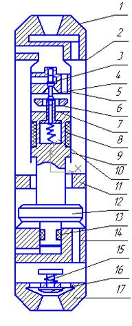
Fig. 1.1 - Hydrovibrator of a DPI design

1.1.Hydrovibrator of a DPI design
2.Description of the developed mechanism
Relevance master's work
Drilling wells in the fields of coal mines in Donbass held mainly in the complicated conditions which are caused by the presence of absorption bands of both natural and anthropogenic origin. Due to delays in identifying acquisitions arises well sludging and, as a consequence - clamps drilling tool sludge. Practice shows that quite effective means of eliminating sticking cuttings is hydraulic mechanisms that excite vibrations of a stuck projectile, which leads to its release. Hydraulic existing mechanisms have several disadvantages due to energy costs in the interchange of the valve group and inhibition striker during a free run. This reduces their effectiveness in carrying out emergency work.
Thus, for the practice of drilling wells in the Donbass very urgent is the development of hydraulic mechanism with high power conditions, which could be used both to eliminate the sticking of the drill exploratory wells. This will improve the technical and economic performances of emergency work and drilling in general. According to this the project of hammers improving in order to remove stuck pipe in wells is relevant.
The purpose and tasks of the master`s work
The purpose of the work - to improve the methods of calculation hammers to eliminate sticking with the hydraulic valve permutation groups, clarifying the laws of its work, the development of practical design and technology of its application.
Research tasks:
1. Analysis of current state hydraulic mechanisms for the elimination of stuck pipe in wells.
2. Analysis of existing calculation methods hydraulic mechanisms for the elimination of stuck pipe and drilling.
3. Improving methods of calculating hydraulic mechanism taking into account the peculiarities of its working cycle.
4. Improving the design of hammers to eliminate stickings and technology of its use.
Possible results which are expected during performance, their novelty and significance
New results:
- Improved method of calculating hydraulic mechanism for the elimination of stuck pipe in wells.
- Design of improved hydraulic mechanism and technology of its application.
The value of the work is to develop a method for calculating hydraulic mechanism with the hydraulic valve permutation group and the justification of design parameters and application technology.
Scheduled testing results (participation in conferences, filing papers to contest the publication, filing for an invention, etc.)
Participation in the republican scientific-technical conference of students "Drilling", the forum of students drillers. Submission to the contest of student research projects.
Currently there are a lot of devices to eliminate the sticking of drilling tools in the boreholes. These are mainly vibration and percussion instruments.
Depending on the location relative to the mechanism which transmits vibrations, surface and submersible hammer mechanisms are distinguished[5].
According to the type of drive all the mechanisms are divided into mechanical, electrical, electromechanical, hydraulic, electro-hydraulic, pneumatic, vacuum compression, electromagnetic, and magnetostrictive[3].
Most rational drive for the conditions of exploration drilling is hydraulic, not requiring special equipment and mechanical and electrical, energy transformation in which isn`t complex, but they require additional equipment[8].
In the given work, hydraulic mechanism is designing[1]. This type of mechanism is the most abundant and diverse in its design features, implementation of schemes and systems for energy conversion of fluid flow in forced oscillations[10].
Hammers are divided into single and double action. Hammers of a single action, in their turn, are divided into hammers with direct active course (stroke is applied by the fluid pressure, the return of striker - with a spring) and the reverse active stroke (stroke is applied by spring force, the return of striker - due to pressure of drilling fluid )[2].
Double-acting hammers are distinguished by their valve group controls two working cavities hammers. Hammers with differential piston (hammers of differential action) can be allocated. They are most commonly used in drilling for a simpler design and higher efficiency. Such arrangements are more often used to create beats in two directions[4].
Hydraulic hammer is used as follows: in case of emergency the drill string is disconnected from the stuck core-shell, which is recommended to include in the projectile detached adapter. After detaching and lifting the pipe string to the surface, pre-assembled unit is getting down to the drill string to the stuck point and is joining the pipe string to the stuck tool. After joining the washing fluid is supplied to the drill string and is given preload columns and made an emergency[7].
Let`s consider mechanisms with hydraulic differential action.
Hydraulic hammer (Figure 1.1) may be included in the composition of the projectile in the process of sinking wells or down in the zone of sticking in the event of an accident[9].
Hydrovibrator consists of adapter 1 / 2, the intake and exhaust valve 3 - 6, the pusher 4, the valve box 5, the shank 7 exhaust valve, piston 8, cylinder 9, spring 10, the upper anvil 11 and lower - 14, firing pin 12 with a shank 13, spring 1915 start-up valve 16, the lower adapter 17. It works as follows. In the frame 2 in the original position the firing pin 12 with the shank 13 under the weight occupies the lower end position, so inlet valve 3 is located in a valve box 5, is closed and the final 6 - open. When a pump circulating fluid through the channels of adapter 1 it enters the bottom of the cylinder 9 and raises piston 8 with the striker 12 upward. With the rise of the piston 8 spring 10 is compressed as a block valve is kept in the original position due to fluid pressure on the inlet valve 3. In the upper position the piston 8 strikes the valve 6, which causes a rearrangement of valves: an inlet valve 3, connected to the exhaust valve 6 tappet 4, opens, and the exhaust valve 6 - closes. At the time of rearrangement of valves, the firing pin 12 will strike the upper anvil 11. With this arrangement, valve flushing fluid flows in the upper chamber of the cylinder 9. Since the working area of the piston top is bigger than the bottom, the piston-peen would rush down, with the valve block retained in the top position due to pressure of drilling fluid on the exhaust valve 6. The piston 8, moving down, grabs the valve shank 6 and will move the valve block to its original position. Simultaneously, the firing pin 12 will strike the lower anvil 14. Blows to the upper and lower anvils are transmitted stuck projectile, arousing in it forced vibrations. When you include hydraulic vibrator in the shell it is necessary that trigger valve 16 is to be opened and ensured passage of drilling fluid on the bottom hole in the process of its deepening that is achieved by selecting the rigidity of the spring 15 and the regulation of its pre-tensioners. Closing the valve 16 when starting the machine will increase due to consumption of washing liquid.
Given hydraulic hammer has the following advantages.
To improve reliability due protection of the inlet valve of the velocity head drilling fluid adapter 1 and switchgear are equipped with horizontal baffles, installed at the entrance of the liquid, and the injection channel in the adapter 1 which are shifted according to the mechanism in the direction opposite to the exhaust outlet. full synchronization of the valves is guaranteed, efficiency and reducing consumption of washing liquid to the drive mechanism increase due to small leaks and high utilization of the liquid (0,8-0,9). Simplicity of design has achieved ability to produce expeditions and associations in any machine shop, the ease of startup and operation.
Hydraulic hammer (Figure 1.2) comprises a body 1, which is attached to the upper anvil 2, the lower anvil 3 and the valve box, which is located the inlet valve 9. Valve 9 is spring-loaded relative to the valve box spring 13 and also has a central channel 8, which is the exhaust valve 7, the spring-loaded spring 10.
The piston 5 has the ability to interact with the exhaust valve 7 through the liner 20. While moving the piston strikes the firing pin 6 on the top 2 and the bottom 3 by anvil in turn[6].
Initially, the firing pin 6 is in the lowest position in direct contact with the lower anvil 3. The inlet valve 9 is closed, i.e. located on the seat 18. Exhaust valve 7 is in the lowest position relative to the inlet valve 9. The working fluid through a channel in the adapter, through the discharge channel 15 enters the gap between the housing 1 and the cylinder 4 and through holes in the cylinder 4 comes under the piston 5. In this case, piston 5 begins to move upward by the force due to pressure of the working fluid.
After the firing pin 6, driven by the piston 5, travels a distance that is less than the striker to a small (about 2 mm) size, the exhaust valve 7 closes the outlet channel 19 in the inlet valve 9 which opens, i.e., rises from the seat 18, and the working fluid flows both above and below the piston 5. Under the forces of inertia firing pin 6 continues to move and deals a blow to the upper anvil 2. Because piston area 5 more than areas of difference between the piston 5 and the rod, the piston 5 begins to move downward, because of the possibility of free relative motion of the exhaust valve 7 in relation to the piston 5, the exhaust valve remains closed.
After the firing pin 6 will get through the distance that is less than stroke of the striker by a small amount, shank 20 breaks the exhaust valve 7, the exhaust port 19 opens and inlet valve 9, through the action of spring 13, closes. Under the forces of inertia firing pin 6 continues to move and strikes at the bottom of the anvil 3. Then the cycle repeats. The advantage of this mechanism is to facilitate the interconnection of an outlet valve and firing pin, as well as reducing the size and mass as a consequence, the exhaust valve which will lead to more stable mechanism and the reduction of energy consumption for a permutation of valves. Also, this method of interaction exhaust valve and piston (connecting through a finger) allows for replacement of the exhaust valve with the least amount of time.

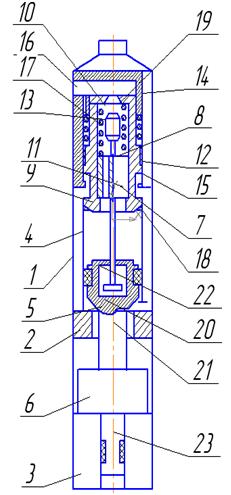
At the Department TTGR a construction of hammers by O.Y. Toder was introduced (Figure 2.1), in order to eliminate stickings.
Hammers contains a body 1 with the top 2 and the bottom three anvils, 4-cylinder, piston 5, located in the cylinder 4 and connected with striker 6 and the rod 7, exhaust valve 8 installed in the brisk 6, the inlet valve 9 with spring 10 and seal 11, located at the top of the cylinder 4. Compression 11 of an exhaust valve 9 forms a cavity 12 and a high-low pressure 13. The inlet valve 9 has a through channel 14, and two in places on the outer and inner surface, and outside the inlet valve seat 9 interacts with the upper part of cylinder 4 and the inner seat with drain valve 8.
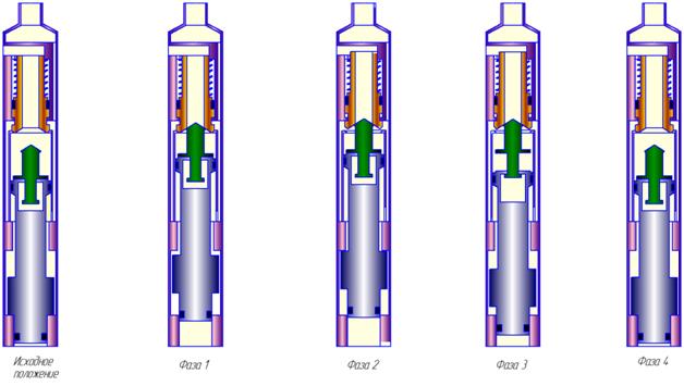
Hydraulic hammer works as follows(Figure 2.2).
Initially, the striker is at the bottom position. The working fluid arrives at the piston and the striker starts to move upwards. The liquid from the head-end cylinder pushes into the hole. Exhaust valve moves upward together with the striker before the interaction with a seat on the inner surface of the inlet valve, closing the exhaust port in it. Through interaction with the discharge valve inlet valve is separated from the top of the cylinder. In the resulting gap between the top of the cylinder and inlet valve enters the liquid from the cavity pressure. Valves jointly move up the value of the intake valve, compressing the spring. Due to the fact that the area of the inlet valve plate is practically equal to the square wave, then in order to open it and to move up a little power is needed, which will be enough to compress the spring. The firing pin strikes the upper anvil.
After the valves have moved upward, the fluid flows as in a piston, and in the head-end volume of the cylinder. Due to the fact that the working area of the piston top more than the bottom, its bullet starts to move downward. At the same time valves are held in a top position by fluid pressure. After firing pin shanks capture the exhaust valve and tear it from the intake valve opens the exhaust channel and the system pressure drops. Peen goes the distance remaining to the lower anvil by inertia and causes it to blow. Exhaust valve is returned to the lower position, and inlet valve spring moves downward to the interaction with the upper part of the cylinder. Collection of fluid in the cavity above the piston is stopped and the duty cycle is repeated.
The advantages of the developed device:
- reducing the loss rate of the striker on a free during the permutation valves, both due to a decrease in the free running as well as by reducing the hydraulic resistance of the valve group, since the area of the inlet valve does not dependent on the area ratio of the piston and rod, and may be equal to the area of the cylinder.
- increasing of the reliability of the hammers by facilitating its launch as a permutation of hydraulic valves do not require co-moving firing pin and valve.
With the help of the developed program Delphi counted parameters of hammers: efficiency, cost of power, pressure drop, the velocity of the hammer, the frequency of shocks, energy single strike.
The calculations take into account the peculiarity of the working cycle - increased time rearrangement of valves in the course of the hammer up , so instead of the formula was proposed by the refined formula
 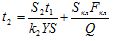 .
.
where S2 - free play striker as it moves up;  - loss factor rate of the striker on a free course; S – stroke of the striker, Y-dimensionless parameter, t1 - the working time of the striker.
During the striker up it will spend more time than during the hammer down. This is due to the fact that during the rearrangement of valves, part of the fluid will be expended on their transposition, as well as the amount which is to be released under the permutation is filled with fluid and pressure is applied to the valve group.
As a result of the construction work, the hammers design of a double differential action was developed, which has a simple design, less energy loss and rearrangement of valves in the free course.
During the work, the method of calculation hydraulic mechanism with a hydraulic valve permutation group was developed, justified the design parameters and technology applications.
Further research is planned to refine methods of calculation of dynamic processes in the course of the drill for the elimination of stickings in the borehole.
Коломоец А.В. Предупреждение и ликвидация аварий в разведочном бурении. – М.:Недра, 1985, –224 с.
Неудачин Г.И., Квашин Е.В. Основные вопросы работы гидроударных буровых механизмов дифференциального действия // Сб. Совершенствование техники и технологии бурения скважин на твердые полезные ископаемые. – Вып.12,- Свердловск,1989.-с.73-78.
Калиниченко О.И., Комарь П.Л. Породоразрушающий и металлообрабатывающий инструмент – техника и технология его изготовления и применения. – Сборник статей. Вып.12, - Киев, 2009, с. 44.
Пустовойтенко И.П. Предупреждение и ликвидация аварий и осложнений в бурении. – М.:Недра, 1997.-238с.
Пустовойтенко И.П. Предупреждение и ликвидация аварий и осложнений в бурении. – М.:Недра, 1988.-279с.
Калиниченко О.И., Русанов В.А., Рязанов А.Н., Методика проектирования конструктивных и рабочих параметров забойных гидроударных машин. // В сб. «Совершенствование техники и технологии бурения скважин на твердые полезные ископаемые». – Екатеринбург: УГИ, 1993. – с. 97 – 102.
Самотой А.К. Предупреждение и ликвидация прихватов труб при бурении скважин. – М.:Недра, 1979.-182с.
Самотой А.К. Прихваты колонн при бурении скважин. М.:Недра 1984. – 204с.
Описания изобретений по классам E21B 31/113, E02D 7/10 за 1991-2001 гг.
Калиниченко О.И., Русанов В.А., Каракозов А.А. Hammer and Hammer – vibration Mechanism for Liquidation of Sticking. // Journal of Changchung University of Earth Sciences, 1993. - pp.137-139.