|
|
 Vladimir Dolmatov
Electrotechnical faculty
,
French engineering faculty
Department Electric drive and automation of industrial complexes
Speciality Electromechanical automation systems and electric drive
Hybrid control of a wheelchair
Supervisors of studies: prof. V. Borissenko (DonNTU), E. Monacelli (UVSQ)
Consultants: V. Khomenko, A. Melnik
|
Abstract
Development nowadays robotics, means of automation and innovative mathematical theories demands application of these achievements in practice in those branches which are directed on improvement of life of people with special requirements.
The priority direction to which pay the big attention last decades the leading countries of the world is an introduction of innovative technologies in medicine for the purpose of creation and perfection of the devices helping in movement of people ability to which independent movement is limited.
To show possibility of application of innovative technologies for creation of hybrid control by a wheelchair on the base of the controller of fuzzy logic and strain gauges that make it possible the person with the limited possibilities of movement to move on a wheelchair even at the slightest application of forces.
The person rotates two wheels that to move. If his own forces not enough for moving electric motors start to help him. The more the person applies efforts the big help to him rendered by motors. For full-blown work it is necessary two motors for a chair: for each of two wheels. If there will be a necessity to turn round then the person turns one wheel in one direction and other in another direction, therefore is necessary that the electric drive ensured a backspacing. If the person goes down from an inclined surface and it is necessary to slow down speed of movement it puts hands effort to rims of the wheels directed in opposite direction to movement. For simplification of the given maneuver braking process is picked up by motors increasing the total brake moment. Braking will be carried out by transition of motors in a mode of plugging. When the person moves on a wheelchair at the expense of own force (the electric drive at the same time is not involved) then motors work as generators constantly recharging the accumulator.
The main problem connected with control by a wheelchair is a definition of the force put by the person for rotation of wheels. In article [1] has been offered the interesting method of definition of this force by means of sensor of the torque attached on the main axis of a wheel:
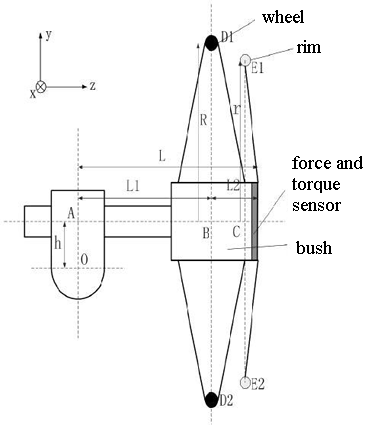
This way allows with sufficient precision to define the torque put by the person for rotation of a wheel, but it is difficult realised on practice as demands replacement of a manner of fastening of a rim to a wheel. We have accept decision to use a noninvasive method of reception of the information on size of force and instead of the torque sensor to use sensors forces (strain gauges) which fasten on the brads connecting a rim with a wheel:
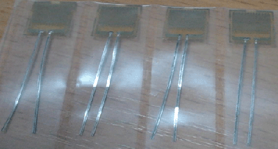
In the course of rotation of rim with a wheel to take place enough strong bending strain and torsional strain. It is possible to measure them if to paste to brad the strain gauges in such order: two in one row on the one side (work on compression) and two from an opposite side of brad (work on stretching):
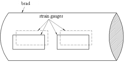
It is necessary to fasten a brad directly to a rim so that resistors settled down along directing of rotation to measure radial deformation of a brad:

In turn strain gauges on a brad have the bridge scheme of connection (fig. 5) as the bridge scheme meets the requirements of exact measurement of size of deformation of strain gauges and gives the least error:
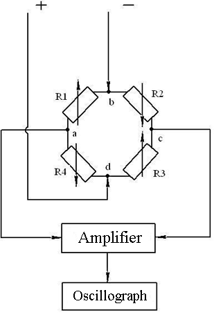
At deformation of a brad equality R1*R3=R4*R2 will not remain, the bridge becomes unbalanced, between points a and c there will be a difference of potentials and on the booster signals will come.
To receive the exact information on the force puted to a rim it is necessary to use at least three brads from six possibles with the sensors pasted on them. These three brads will be placed on a rim in the following way:
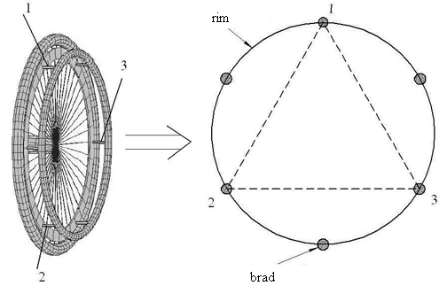
In the end the connection scheme will get:

The bridge will be counterbalanced if equality will be keeping: (R1+R2+R3)*(R10+R11+R12)=(R4+R5+R6)*(R7+R8+R9).
The question of a principle of command of chair is interesting. Me was accepted the decision to make up the command scheme to taken advantage of the approach made by authors [2]:
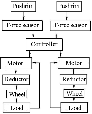
In work [2] authors used in their system the direct current motor with a reductor. Me was accepted the decision to take advantage of their approach but according to my system to take a direct current motor with constant magnets on the stator. This type of the motor has many advantages: simplicity of the device and control, the big starting torque, regulation of speed in a wide range. Braking of such motor will be carried out by opposition circuit:

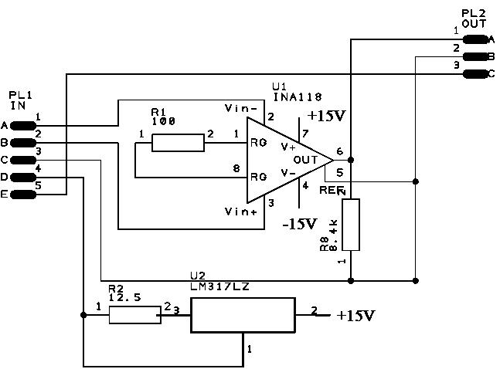
As for a signal going from strain gauges on the controller of the fuzzy logic it is very weak, therefore it must to amplify. In the work i use the amplifier developed by postgraduates Khomenko V. and Melnik A. having amplification factor 500 and eating from two batteries in 9 V:
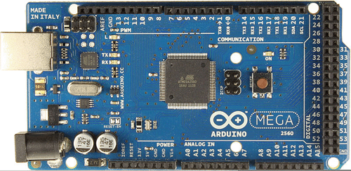
Controller of fuzzy logic is formed on the base of input-output board Arduino Mega 2560 having software environment Processing/Wiring:
We have established by experimental way that at effort in 4 kg the signal in 0,1 V comes on the controller, that allows to use in the further calculations proportionality factor: 0,1/4=0,025 (V/kg).
For work of all system the question connecting with control by wheelchair by means of fuzzy logic is very important. In work [3] authors have shown on example as the fuzzy logic works. According to this example we had been created our structure of the controller of fuzzy logic:
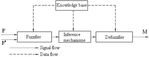
Force and his derivative (push) in volts goings with strain gauges moves on input of this controller. Exit is the torque of motor:
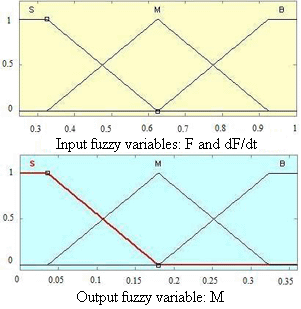
Input and output variables consist of three terms: S (small), M (medium) and B (big):
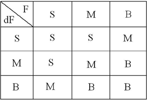
The controller of fuzzy logic will work in the range of the force maked by the person from 10 to 40 kg.
To work of all system the question of a choice of the motor and reductor is very interesting. To orientated on the motor of the electric chair standing in a lecture hall 105 i've chosed the motor to myself from the mass-size reasons: P = 150 W, w = 4000 rpm, Ìn = 0,36 N*ì. According to it the reductor with the transfer relation 100 has been chosen.
The wheelchair with hybrid control on the base of the controller of fuzzy logic has a some advantages in comparison with the electric chair operated by joystick: smaller expenses of a resource of the storage battery (changeable work of motors and periodic additional charge of the accumulator during movement), more simple mechanism of control of turn intuitively understandable for the user. A unique problem of a wheelchair with hybrid control are complexities in realisation of an intellectual part of a control system.
At the moment of a writing of the present abstract the work of master is not ended yet. Definitive end of work will take place in december, 2012. In the near future i'm gonna simulate a control system of a wheelchair in software environment Matlab and on model to show work of the direct current motor from the controller of fuzzy logic and also realise all this system in the practice.
|