
Abstract
Content
- 1. Manipulator as an object study
- 2. Real-time operating systems
- 3. The principle of implementation of real-time program control
- 4. Position electric drive
- Conclusion
- References
1. Manipulator as an object study
Manipulator control system actuators provide motion of the executive body for a given spatial trajectory by controlling the movement of individual links of the manipulator. Each link is equipped with electric drive and sensors for motion control. Set on the motion of the links provided from the control software device. Figure 1 shows the functional diagram of a motion control system links three-tier manirulator, which allocated only portable coordinate. Defining impacts q13, q23, q33 are fed to the control units CB1 ... CB3 electric M1 ... M3 [1].
G1 ... G3 ensure the implementation of the required type of motion (linear or angular) of the links. This movement is determined by the generalized coordinates q1, q2, q3. Position sensors can be installed on the links and the manipulator motors.
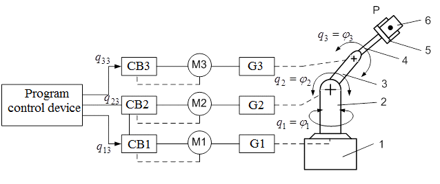
Figure 1 – The functional diagram of a motion control system
Implementing motion control systems of manipulators, seek to ensure that the inertial properties of the actuators and the links did not make any distortion to the specified trajectory of the gripper. For this purpose use electric drives, which have a large bandwidth. These properties are servo. However, the dynamic properties of the manipulator as an object of control does not allow you to do this explicitly by considering the links of the manipulator control as stand-alone system. Because of the Coriolis and centrifugal forces of inertia for a number of schemes of manipulators having the dynamic relationship of links that must be considered when designing control systems [1].
2. Real-time operating systems
Control of electromechanical systems is significantly different from the usual data on the computer. This processing follows the events in the object of control. Digital control system must be fast enough to respond to external events and are constantly processing the input data stream, often without being able to change the speed of their arrival. The same time the system should provide and perform the other, the auxiliary functions – information exchange, processing, preservation and archiving of data, its display, an appropriate response to certain signals, etc. For real-time a mode of computing devices, using special programming techniques because of features inherent in this mode. These features include the fact that real-time system contains not one but several programs, each of which is responsible for solving a particular task, and the relationship between these programs can be very difficult. In addition, the order of the commands of the real time program can not be determined in advance, since it depends on external events and can be changed by interrupts. Therefore, the time required to compute each cycle of operation may vary considerably [3].
The basic requirements for real-time are as follows:
- high priority should always be performed first;
- inversion of priorities should be excluded;
- processes and threads, the execution time which can not be planned, will never be fully occupy the system resources.
To provide real-time operating systems can be implemented the following requirements [4, 5]:
- support for dynamic priorities (which can be changed during the task execution) in a preemptive multitasking kernel (for both processes, as well as for flows);
- the possibility of priority inheritance;
- the possibility of displacement of the core tasks of the operating system;
- Interrupt latency is bounded by (the time during which interrupt is allowed – is the processing time of a critical section of code);
- implementation of operating system services with a priority that is assigned to a customer service.
The most common in the programmable logic controllers and computers for solving problems of automation are operating systems Windows CE, QNX and ОS-9.
3. The principle of implementation of real-time program control
Consider the implementation of
the principle of program control in real-time coprocessor module SM-Application,
which is used to control the frequency converter (Control
Techniques). User application
consists of separate sections (tasks) that are executed in strict
sequence. These sections are (in order of priority): Initial
,
Event
,
Pos
,
Clock
and Background
. When power is applied first to the statements recorded in the section
Initial
,
which are given values of constants and initial values of the
signal control system, and is defined by its configuration. After that,
begin to run real-time tasks of section Pos
(there may be several such Pos0
and Pos1
)
and Clock
.
Instructions are placed in these sections, cyclically repeated at fixed
intervals of time (discrete periods). The period for the discrete task Clock
(T∂1)
can take integer values from 1 to 200 ms, and for tasks Pos0
and Pos1
(T∂2)
– strictly fixed values: 250 ms, 500 ms, 1 ms, 2 ms, 4 ms
and 8 ms.
Regulations sections Event
have the highest priority, so their task contain very small number of
instructions. They interrupt the operation of section Pos
and Clock
,
and only at the end of their performance management program continues
the interrupted instruction sections Pos
and Clock
.
Thus, in the sections Event
advisable to put the algorithms of certain events, such as emergency
situations.
Background
– is a background task. It runs only in the pauses between
the instructions of the other sections. This task is organized in the
form of an infinite loop. If it is completed, it will no longer run.
In figure 2 introduced the concept of mutual termination of tasks [6].

Figure 2 – Time diagram of the implementation specific instructions
4. Position electric drive
In motor drives are widely used industrial manipulators positional system. A characteristic feature of these drives is the availability of units of measurement and control of position. Implementation of the mode of positioning in the modern complete electric drive is performed by means of intelligent expansion modules controller drives.
With respect to the angular displacement in figure 3 (a, b) shows the timing diagram rectangular acceleration ε(t), as well as time diagrams of velocities ω(t) and displacement φ(t) for modes of small and large positioning mechanisms. In figure 3 (c, d) - parabolic time tachogram for the same modes with the assumption that the resisting moment is equal to 0 and in figure 3 (e, f) - parabolic temporal tachogram with jerk limitation.
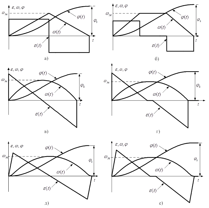
Figure 3 – Positioning diagrams
Conclusion
Thus, the task of developing control systems of electromechanical manipulators with improved dynamic, static and power conditions is important.
It promotes the development of the decision giving the devices that implement the optimal control laws in real time.
The aim is to reduce overhead electricity, increase the positioning accuracy and improved dynamic properties of the actuator position through the development of optimal digital algorithms of the control action in relation to a subordinate position control systems.
To achieve this goal it is necessary to solve the following tasks:
- development of a digital control algorithm of the position electric drive taking into account quantization effects on the level and extrapolation;
- theoretical rationale for the choice of digital integration algorithms for the setpoint position, which forms the best in performance or loss of thermal control laws;
- development of methods of program implementation of digital control system position in real time.
Master's work hasn't been complete at the moment of writing this abstract. Final completion: December 2012. The full text of the materials on the topic can be obtained from the author or his consultants after that date.
References
- Белов М.П. Автоматизированный электропривод типовых производственных механизмов и технологических комплексов: учебник / М.П. Белов, В.А. Новиков, Л.Н. Рассудов. – М.: Изд. центр «Академия», 2004. – 576 с.
- Олссон Г., Пиани Д. Цифровые системы автоматизации и управления – СПб.: Невский диалект, 2001. – 557с.
- Ишматов З.Ш. Микропроцессорное управление электроприводами и технологическими объектами. Полиномиальные методы: монография / З.Ш. Ишматов. Екатеринбург: УГТУ-УПИ, 2007. – 278с.
- Денисенко В.В. Компьютерное управление технологическим процессом, экспериментом, оборудованием. – М.: Горячая линия – Телеком, 2009. – 608с.
- Сорокин С. Системы реального времени // Современные технологии автоматизации. №2, 1997, с. 22 – 29.
- Руководство пользователя SM-Applications. Дополнительный модуль для Unidrive SP. Редакция 4. – 2004. – 113 с.
- Толочко
О.И. К
вопросу об изменении типовых структур цифровых систем управления
комплектными электроприводами / О.И. Толочко, П.И. Розкаряка, Н.М.
Горобец // // Наукові праці ДонНТУ. Серія:
Електротехніка і енергетика
. – Вип. 10 (180). – Донецьк: ДонНТУ, 2011. – C.188-193. - Толочко О.И., Коцегуб П.Х., Розкаряка П.И. Синтез задатчика положения с ограничением рывка при учете статического момента // Вісник Кременчуцького державного політехнічного університету: Наукові праці КДПУ. – Кременчук: КДПУ. – 2008. – №3 (50). – Ч.1. – С. 58-63.