
Equipment of chemical plants and enterprises of build materials
Ensuring of anthropogenic safety of chemical equipment is one of the most pressing problems that arise in any by-product coke plant. This is directly dependent on the economic efficiency and stability of production.
In this connection, there is need for a more detailed study of not only technological, but also the degradation processes that directly affect the durability of structural elements. As well as improving methods of their calculation.
Despite the large number of various methods for calculating this type of equipment, the error in them is great. Inaccuracy of the calculations leading to increased costs of materials and to the impossibility of predicting the residual life of the technical object.
The difficulty is that the same type of structural elements often works in different conditions: temperature, pressure, velocity, with a variety of environments. Resulting degradation species, their level and emerging defects of the same structural elements differ markedly.
In the calculations for estimating the strength of the structural elements of technical objects is using the classic formulas that can give an adequate result only in the absence of degradation processes. Because of what the real working stresses in the material are more design stress. When the equipment is operated in such circumstances the level of anthropogenic safety can be brusque reduced. All this makes it necessary to develop a methodology for calculating the probability for the strength assessment, which will take into account changes in relevant parameters that will anthropogenic safety in by-product coke plant shops.
The research goal is Ensuring of anthropogenic safety in a primary cooling zone of the coke oven gas of by-product coke plant capture shop through the development of more accurate methods of calculating the design elements of the equipment as an example the calculation of the primary tube gas cooler.
The main tasks of the research:
The object of study: primary tube gas cooler, located in the capture shop public company Avdeyevka by-product coke plant
.
Machine room of capture shop number 2 public company Avdeyevka by-product coke plant
(Figure 1) is designed to evacuate gases from the coke ovens, and create the necessary pressure to move the coke oven gas through the equipment of chemical shops and gas conduit to the consumer [1].
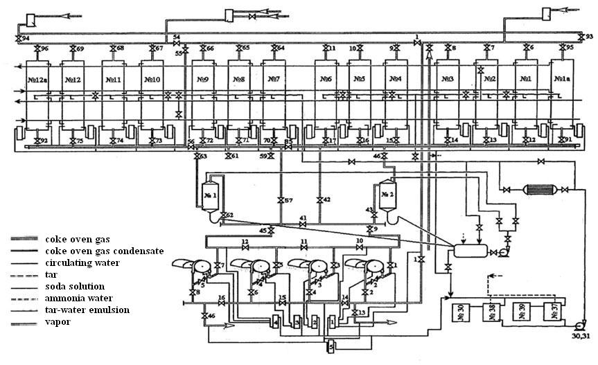
Figure 1 – Technological scheme of the capture shop mashine room of public company Avdeyevka by-product coke plant
The equipment and the gas conduit are located to the supercharger of coke oven gas, under vacuum, and after them - under pressure.
Chemical products of carbonization (coke oven gas), formed by thermal decomposition of coal without access of air, out of the coke ovens underroof space through the risers in a gas collector with temperature at most 820 °С.
In the gas collector coke oven gas is cooled to a temperature of 80 – 85 °С ammonia-tar water, which is supplied from the gas collector for irrigation pumping condensation.
Ammonia-tar water cools the gaseous products of carbonization at the cost of the evaporation part of what is possible at a sufficiently high temperature of 70 – 75 °С.
Upon cooling of coke oven gas occur resin vapor condensation, as well as the wash-out of solid particles of coal and coke with are mixed with tar to form sludge.
The cooled coke oven gas, saturated with water vapor, condensed tar with sludge and ammonia-tar water from the gas collector comes by gas conduit to the gas separator. From gas separator ammonia-tar water and tar with sludge comes by the mechanized clarifiers for the separation of ammonia-tar water, tar and sludge.
Coke oven gas, water vapor and tar mist out of the top of the gas separator and sent by gas conduit to the tube gas coolers. In the tube gas coolers coke oven gas is further cooled: in 2 of the upper sections is cooled of the soda solution, fed from a desulfurization shop number 2, and 2 of the lower sections of the circulating water is cooled.
In gas coolers cooling of coke oven gas is circulating water, which after cooling on water-cooling tower CWS is advance into the pipe space gas coolers with a temperature of 27 °С. In the process of coke oven gas is cooled in the gas coolers condensation of water vapor, the release from gas tar, as well as the dissolution in the formed condensate a certain amount of ammonia, hydrogen sulfide and carbon dioxide.
In addition, a large number of naphthalene is condensation, part of which is absorbed by the condensed tar; part is deposited on the walls of the tubes.
The heated circulating water coolers after gas coolers supplied to water-cooling tower CWS, cooled and re-fed into the gas coolers.
In gas coolers, coke oven gas is cooled to a temperature of 25 – 35 °С,and the circulating water is heated to a temperature of 30 – 42 °С. Formed by cooling gas condensate flows through the water seal on the pipeline in the collections of the condensate number № 37, 39 (30,38).
Removal of naphthalene sediments from the surface of the cooling tubes is carried out by washing them tar-water emulsion.
To avoid the formation of scale on the inner surfaces of tubes in the form of poorly soluble in water СаСО3, formed by heating the water as a result of the expansion is in its Са(НСО3)2 is necessary to avoid raising the water temperature at the outlet of the gas cooler above 42 °С.
The main responsibility object in the zone of the primary cooling zone is a tube gas cooler with horizontal tubes submitted public company Avdeyevka by-product coke plant
. It is a apparatus with dimensions of 24,7x3,6x3 m, has a capacity of 20000 m3/h [1].
Case a gas cooler (Figure 2) has a rectangular cross section, the two vertical walls which are fixed flare tubes 3 [2]. Walls gas cooler with stiffening ribs 2.
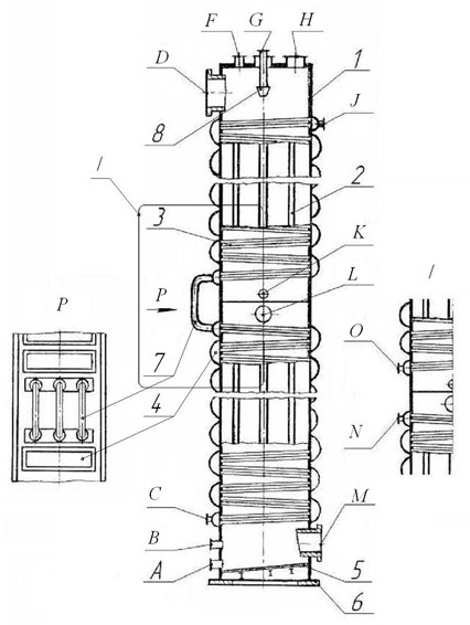
Figure 2 – The primary gas cooler
Tubes are separate into bundles, which are connected by removable covers 4. At the bottom of the gas cooler is a flat bottom 5, inclined at an angle of 3 – 4 ° to facilitate the removal of condensate. The case is set on raft with pillar 6. For ease of transportation, gas cooler height is divided into four sections, which are welded together during assembly. Tubes bunches of sections are connected by transitional bends 7.
Coke oven gas is enter in the connecting branch D gas cooler with a temperature of 82 °С under a pressure of 0,095 MPa, moving from top to bottom in the tube space and out in the connecting branch M with a temperature of 35 °С. Water is pumped from the bottom to the connecting branch C, passes successively all the bundles of tubes, fitting out in the connecting branch J and gravity is directed to the water-cooling tower. As the tubes are inclined at an angle of 1 ° to the horizon, the condensate formed during cooling of coke oven gas flows along each tube, and the whole top-down and washes away the deposits of naphthalene. Condensation from the gas cooler is displayed through connecting branch A. In addition to flushing tube flow is provided in the connecting branch G ammonia-tar hot water spray nozzle 8, and the connecting branch K hot tar, which is a good solvent for naphthalene. When steam is fed to the steam cleaning connecting branch B. For maintenance and repair of gas cooler designed hatches H and L. When steaming and blowing cooler gas used by air vent F.
The section construction of PGC can clearly see below.
")
Figure 3 – Section of the primary gas cooler
In the public company Avdeyevka by-product coke plant
modernized this design by removing the crossover bend between the second and third sections of the gas cooler and found it f connecting branch N and O. As a result, water enters through the connecting branch C and out through the connecting branch N. A soda solution is fed to the desulfurization shop on connecting branch О and exits through the connecting branch J.
Coke oven gas is a product of dry distillation of coal in coke ovens [3]. It consists mainly of hydrogen, methane, heavy hydrocarbons, carbon monoxide, carbon dioxide, oxygen and nitrogen. In addition, the raw coke oven gas contains tar, naphthalene, ammonia, benzene, hydrogen sulfide and water, which condenses in the equipment of chemical shops in and out.
Coke oven gas is a combustible gas, it is explosive in mixed with air (the flammability limit from 6 to 30%), and fire-hazardous (the flammability temperature is 600 – 650 °С), is toxic. The maximum permissible concentration of its components should not be more (in mg/m3):
300 СН4, 50 СmНn, 5 С6Н6, 20 СО, 10 H2S, 0,3 HCN, 0,3 С6Н5ОН, 5 С5Н5N.
Combustible part of the coke oven gas is hydrogen, methane, carbon monoxide and heavy hydrocarbons. Carbon dioxide, oxygen and nitrogen in the combustion of coke gas do not burn, and heated to a temperature of combustion gas, so the heat is expended for their warmth. The maximum heat of combustion of coke oven gases 4300 – 4500 kkal/m3,the relative density of 0,45 – 0,46 kg/m3.
After removing the chemicals and cleaning of coke oven gas is hydrogen sulfide gas blowers with transport to steel mills, where it is used as fuel for the smelting of steel in open hearth furnaces and ingot heating in furnaces of rolling mills. Surplus coke oven gas used for household purposes, or burned in industrial boilers.
The reverse process water is a suspension. There are different kinds of particles, adversely affecting the pipeline and equipment with which it interacts [4]. The cooling water is characterized by the following parameters (Table 1).
Table 1 - Indices of technical water and their impact on equipment
| Indicator | Impact |
| Temperature | Limiting temperature of the water used to cool the heat exchangers, due to economies of their work and process requirements |
| Suspended solids | When the content of more than 50 - 100 mg/l can cause contamination of heat exchangers |
| Oxidability | The value of oxidation more than 5-8 mg/l of oxygen indicates a possible source of contamination by sewage, indicates the possibility of organic fouling in a water-cooled heat exchangers |
| Stiffness | Increased carbonate hardness of water added in the circulating water systems leads to the deposition of calcium carbonate in heat exchangers and cooling devices (cooling tower, spray pond). When heated, the dissolved calcium and magnesium salts - salts of hardness, go to the scale, if these processes occur in the tubes, the heat exchange process breaks down. |
| The active reaction (pH) | Low pH values usually cause corrosion of tubes, in conjunction with other indicators of water quality (temperature, total acidity, calcium and dissolved residue) gives an indication of the ability of the water deposit in the water tubes and cooling equipment, or calcium carbonate, washed cause corrosion of metal surfaces to form them mounds of glandular growths. |
| Having silicic acid | Its presence prevents the use of water for boiler feed high pressure (due to the deposition of silica scale on the walls of boilers and turbines) |
| The presence of free carbon dioxide | Can cause corrosion of concrete structures and water tubes. Dissolved oxygen: metal enhances the corrosion of boilers, heat exchange equipment, heating and water tubes. |
| The presence of hydrogen sulfide | Promotes clogging and abrasion of pipes |
| The presence of undissolved particles of the mechanical (sand, rust, sediment, colloids) | Causes corrosion of tubes and their overgrowth as a result of sulfur bacteria. |
In addition to the cooling of coke oven gas technical water soda solution desulfurization shop is heated in PGC.
The spent soda solution desulfurization shop contains hydrogen sulfide and hydrogen cyanide, as well as ballast salts, which are products of oxidation of H2S and HCN [5].
Evaporation of the solution is containing the substance of the first and second class of hazard - hydrogen cyanide and hydrogen sulfide.
The equilibrium concentrations of hydrogen sulfide and hydrogen cyanide over the spent solution are several times higher than the maximum permissible concentrations of these components in the working area.
Excessive accumulation of salts in the ballast of the absorbent solution leads to precipitation of crystals and clog the equipment, as well as to reduce the absorptive capacity of the solution and the deterioration of coke oven gas purification from hydrogen sulfide. To maintain the concentration of irrecoverable connections within 120 - 160 g/l of the absorbent solution is required to output from the cycle, and to compensate for the loss of alkaline components in the system must be added to a fresh solution of soda or potash.
Consumption of chemicals to clean coke oven gas depends on the content in the H2S, HCN and О2, as well as on the temperature and characteristics of the technological scheme and hardware design. For practical data flow ash is 40 - 50 kg per 1 ton of captured hydrogen sulfide.
The average composition of the absorption solution vacuum - carbonate desulfurization is found in table 2. Specific consumption of the absorber is 3 - 4 liters per 1 m3 of gas.
Table 2 - Composition of the absorption solution vacuum - carbonate desulfurization
| Components. | Content in the solution, g/l |
| Me2CO3 | 35 – 40 |
| MeHCO3 | 15 – 20 |
| MeHS | 1,5 – 2,5 |
| MeCN | 1,0 – 1,5 |
| MeCNS | 80 – 120 |
| MeCOOH | 20 – 40 |
| Me2SO3 | 10 – 12 |
| Me2SO4 | 3 – 6 |
| Me4Fe(CN)6 | 10 – 15 |
In some plants for the preparation of the absorption solution is a mixture of soda and potash in the ratio 1:1. Experience has shown that with this solution of the absorption probability of salt crystals is sharply reduced, improving performance of processes of absorption and regeneration, reduced reagent consumption and the amount of wastewater.
It always made high demands for reliability and safety of chemical enterprise equipment. It is connected therewith that machines and devices operate under heavy conditions: pressure, temperature, corrosive medium. Along with heavy conditions in any equipment a number of processes run which negative influence on the operation life of constructional its elements. It is inadmissible for enterprises in this industry because any failure can lead to depressurization of equipment, emission of harmful and hazardous substances into the atmosphere, will be causing great economic loss, will have a negative effect on the ecological situation and may affect on the population health living near the enterprise [6].
A whole number of technological processes flows in PGC. First of all, it's heat exchangers, in particular heat transfer from the coke oven gas to the water through a separating wall, which is accompanied by a number of other processes: the condensation of water vapor from the coke oven gas, the condensation and separation of pitch vapor residual, mass transfer. Heat transfer is carried out in pipes, and the temperature of the coke oven gas decrease, so that the liquid phase – the pitch – is escaped from gas and absorbing naphthalene it is formed a complex corrosive substances. The absorption of ammonia, carbon dioxide, hydrogen sulfide, hydrocyanic acid and other components containing in the coke gas happen by the condensation of water on the pipes surface. The combination of different acids is generated, that also promote destruction of the PGC elements.
Degradation processes unavoidable flows along with the technological processes. They are corrosion of casing, the outer and inner surfaces of pipes, scaling, a material aging.
The apparatus casing was subjected to corrosion increasingly. With the outside – chemical (rusting of metal elements under the influence of aggressive medium) and electrochemical (under the influence of rain water and a condensate with the salts ions and acids dissolved in these) corrosion, with the inside – the destruction under the action of aggressive substances in the coke oven gas. The pitch is escaped upon cooling the coke oven gas, it absorbs naphthalene and generate a concentrated alkali, which reacts with the elements of PGC structure and leads to them intensive corrosion. The presence of cyanic hydrogen also accelerates the degradation process of the casing and pipes (Fig. la). HCN dissolves partially in ammonia-tar water with formation of the toxic ammonium salts of cyanide and thiocyanic acids.
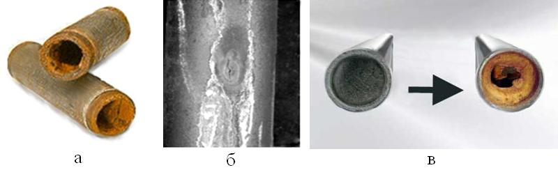
Figure 1 - Types of pipes degradation in the primary gas cooler:
a) chemical corrosion, b) an arising; c) scale
Pipes also undergo corrode from the inside under the action of the impurities that are in the industrial water and soda solution. All this leads to the destruction of the metal casing, an arising in the pipes (Fig. lb). The soda solution through an arising will go into the gas condensate, which will have an adverse effect on the operation of mechanized clarifiers, biochemical waste treatment and will complicate of pitch processing. Intensive corrosion of pipes promotes to the accumulation of ballast salts in the soda solution and deterioration its absorption capacity.
Another type of degradation of the PGC elements is the formation of solid deposits on the inner walls of pipes, that is scaling (Fig. 1c). The formation of a layer of scale reduces the flow area of pipes, in so doing their roughness increase and the hydraulic flow regime changes. The thermal conductivity of scale is less in the tens, often hundreds of times than the thermal one of steel, of which is manufactured heat exchangers. This leads to the deterioration of the heat transfer conditions in particular disturbance of the basic technological process. The phenomenon of scale also leads to an increase of turbulence and the significant purification costs of pipe.
Ageing processes (degradation of the structure and the mechanical properties) flows actively to the metal under the influence of high temperature, pressure, corrosive medium, as well as subject to the continuous operation of equipment. It adversely affect the strength of elements of equipment and may be cause its accidental destruction [7].
After analyzing the above, it may be noted that the primary gas cooler is complicated equipment by the operation. It operated in hostile mediums and gradually ruptured in consequence of the complex processes operating, both technological and degradation. It brings not only great economic losses, but increases the failures and accidents risk and deterioration of ecological situation. Ensuring safe operation conditions and service-life extension of the given apparatus is very actual.
This master's work, namely its computational part, is not completed yet. Final completion: December 2012. The full text of the work and materials on the topic can be obtained from the author or his head after this date.