
Реферат по теме выпускной работы
Содержание
- Introduction
- 1. Relevance of the topic
- 2. The purpose and objectives of the study
- 3. Structure and operation gas turbine engine TW3–117
- 4. Synthesis of composite technology to repair and restore the blades gas turbine engine
- 4.1 Classification of the blades
- 4.2 Types of damage to the blades
- 4.3 he existing technology of repair and restoration the blades gas turbine engine
- Findings
- List of sources
Introduction
In modern engineering in the highly competitive domestic and global markets of particular relevance to the problem of engine-building companies have release competitive products. It is necessary to take into account product quality, deadlines and cost of the product[1].
One of the most important tasks to improve aircraft engine is to increase their reliability and service life.
The reliability of turbine engines is largely dependent on the reliability of the compressor and turbine blades, because they are the most loaded parts. The blades are exposed to static, dynamic and cyclic loads, in addition, the turbine blades experience cyclic thermal stress, they work in an aggressive gas environment at high temperature and exposed to gaseous corrosion [2]. Shoulders GTE have complex spatial geometry and made of hard-deformable materials: superalloys, titanium and aluminum alloys. These increased requirements, such as the structure of the metal, its chemical composition, mechanical properties, geometric dimensions, the exclusion of defects (zakovy, backache, burnout, burn marks, etc.) [1].
1. Relevance of the topic
Therefore, increasing the efficiency of gas turbine engine blades, which are under the influence of alternating loads and centrifugal forces, is the urgent problem of our time, which can be solved in a comprehensive treatment of the last transaction of the process. Improved performance on the stage of production is the development and introduction of advanced finishing technology, which provide a significant contribution to the quality of manufacturing products, and therefore to the improvement of its service life and reliability [3].
Gas turbine engines are out of operation at the end of the resource efficiency blades. There are occasions when damage to the blades are small, then you need to restore them. Most regenerative repair are subject to the scapula which damaged the front edge.
The complexity of repair of damaged blades in that location, size and shape of the chips in each case is unique. Therefore, each case of repair the scapula requires an individual approach.
In this paper we propose a way to improve the quality of repair of blades, GTE TW3–117, on the basis of special composites technologies, which are based on the composition of the main features and principles of the synthesis of combined (hybrid), macro-, micro-and nanotechnology-based, functional technology. These technologies include a new class of organizational and technological forms of technology. On the basis of these technologies provides a qualitatively new set of properties of products [4]. The same will be considered methods of repair and restoration of the blades, the classification of the blades, developed a progressive process to restore and repair of blades and is designed device for applying a vacuum ion-plasma coatings.
The scientific value of the work
The scientific value is to establish patterns between operations and the establishment of a rational structure of the process of repair and restoration of GTE blades TW3–117.
The practical significance of the work
The practical significance lies in the fact that an increase in the quality of GTE blades, increasing their durability, wear resistance and increases their service life.
2. The purpose and objectives of the study
Based on the foregoing, the goal of:
Improving the quality of repair and restoration of the blades of gas turbine engine ТW3–117, due to technological improvements to ensure the synthesis of composite technology.
Based on this goal, the basic objectives:
- To analyze the current state of technology support of processes of repair and restoration of gas turbine engine blades TW3–117, based on the synthesis of composite technology;
- Investigate the possibility of increasing the longevity of GTE blades TW3–117 by applying a vacuum ion-plasma coatings;
- Develop a progressive process of repair and restoration of GTE blades TW3–117;
- To design a device for applying a vacuum ion-plasma coating;
- Run experiments to study the properties of wear-resistant vacuum ion-plasma coatings;
- Develop recommendations for improving the technological processes to ensure the repair and restoration of GTE blades TW3–117.
Scientific novelty:
- Establish a link between the operations regularity structure of the composite process for the repair and restoration of GTE blades TW3–117;
- Develop a rational structure of the process for application of vacuum ion-plasma coatings.
Object of study:
The compositional process of repair and restoration of GTE blades
Subject of research:
Establishing a connection between the operations regularity process of repair and restoration of GTE blades
3. The structure and characteristics of the GTE TW3–117
Considered the engine TW3–117 (pic. 1), which was created a whole new level than the gas-turbine engines (GTE) of the second generation. In his introduction for the first time in the Soviet Union had mastered such advanced technological processes such as electron beam welding and cold forming of compressor blades, which are subsequently introduced in the construction of any and all domestic gas turbine engine. Compared with its predecessor TW2–117, engine has 30% more takeoff power with smaller dimensions and weight[5]. The principle of operation of the engine – Compressed air from the compressor enters the combustion chamber, fuel is fed to the same, which is burning, forms a large number of products of combustion at high pressure. Then the energy in the gas turbine combustion gases is converted into mechanical work by rotating blades of a jet of gas, part of which is spent on the compression of air in the compressor. The rest of the work is transferred to the driven unit. The work consumed by this machine is a useful work GTE. [9].
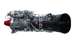
Picture 1 – Gas turbine turboshaft engine TW3–117
TW3–117 consists of 12-stage axial compressor with adjustable inlet guide vanes and guide vanes four stages, an annular combustor, two-stage compressor turbine and a two-stage free turbine. Dust the unit is installed [6]. In the control system used electronic blocks. The engine runs on aviation kerosene grades T–1, TС–1, РT. The oil system uses synthetic oil B–3W.
The major changes introduced to create TW3–117, been [7]:
- the use of controlled guide vanes of the first four stages and inlet guide vanes, allowing a well-coordinated work of the individual stages and a high efficiency (maximum 86%) and high stability margin (almost 22%);
- manufacture of rotor blades of the compressor by a cold rolling, and the guide blades – method of broaching. The method of rolling blades allowed to abandon labor-intensive part of the profile milling, previously used in engine.
- use in attaching the rotor blades of turbines dvuhzubogo castle instead of the usual three-and applied chetyrehzubyh that eliminated the mounting flanges and components, to increase rigidity and reduce its weight;
- used in turbine nozzle-cast vehicles, ensuring high rigidity, high utilization of the metal and the minimum mass, down compared with the sectional structure of almost 25%;
- introduction of ring-type combustion chamber, which exceeded the recommended calorific value, thereby reducing the length of the camera and the whole engine;
- placement of the fuel reservoir inside the combustion chamber, resulting in his weight gain compared with the design of the engine type TW2–117 almost 40%;
- application of contact of graphite seals, shortened the air leakage is almost twice as;
- widespread use of titanium, of which holds about 50% of parts and components (housing and drum compressor housing turbine housing and the diffuser of the combustion chamber, the compressor front support, brackets, etc.), which significantly reduce the mass of the engine;
- the introduction of precise (precision) casting, which provided a significant gain in the coefficient of metal;
- application of electron beam and automatic welding, will significantly reduce the weight of the engine and the high rigidity and high reliability connections.
Engine TW3–117 can be used other than helicopters in various courts of water transport, to drive electric generators and compressors neftegazoperekachivayuschih stations. In the jet case (without the module of the free turbine) engine can be used for drying jet exhaust areas for livestock, buildings under construction, blowing snow and ice on roads, railways, airfields [8].
4. Synthesis of composite technology for the repair and restoration of GTE blades
Composite technology is a special technology based on the principles of composition and characteristics the synthesis of various technology options, which allows you to control the properties of the product and to provide the parameters its quality improvement in areas of technology options for the composition. In this technology, the number directions to improve the quality of products is determined by the number technology options that make up the composite technology. Relations between the stages of designing these technologies hold the iterative and recursive [4].
4.1 Classification of the blades
In the gas turbine engine TW3–117 distinguish between workers, rectifying and rotary compressor and turbine blades. In addition, the compressor vanes are vanes and input, and the turbine – nozzle blades and cooled [10].
Design and technological features of rotor blades (pic. 3) have a fundamental influence on the gas-dynamic characteristics of the engine and the stability (reliability) of their work. Working turbine blades operate at high temperatures, have large static, vibration and thermal stresses. They are both corrosive and erosive action of gases. Given the harsh conditions of the rotor blades and their role in the engine (reliability and service life of turbine blades are usually determining the reliability and life of the engine), to constructive forms of rotor blades, to a method of attaching them to drive to their materials, manufacturing technology and control in the operation of placing particularly stringent requirements[13].

Picture 2 – The model rotor blade, designed in SolidWorks
The blades of the axial compressor rectifying (pic. 3) – fixed or rotating profiled blades, located behind the impeller stage axial compressor and straightening (fully or partially) twisted flow of air coming out of the impeller. The blades of axial compressors are a major element of the rectifying unit rectifying axial compressor. Fixed blades are attached either directly to the housing of the axial compressor, or to the outer circumferential bandage, which in turn is attached to the body of the compressor, or both (external and internal) bandages [12].
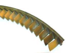
Picture 3 – Rectifying vanes on the bandage
The blades of the axial compressor rotary (pic.4) – movable vanes that can rotate and thereby change the angle of installation when the engine is on the ground and in flight. They are designed to regulate the compressor off-design operation modes is mainly to improve compressor efficiency and sustainability of its work. Rotary blade guide vanes are widely used in single-shaft axial compressors, aviation gas turbine engine to facilitate starting and acceleration of the motor, as well as to ensure the sustainability of its work on the equilibrium, but the off-design modes. [13].
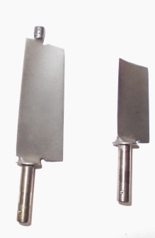
a б
Picture 4 – Rotary blades: а – double-seat; б – console.
Nozzle turbine blades, unlike the workers did not have the effect of centrifugal forces, so the creep resistance in this case is not so important. However, in the past, these blades were broken occasionally by the appearance of cracks or bending, arising as a result of excessive thermal gradients immediately after engine start [14]. At the present time is usually carried out laboratory tests on individual plates of the same profile as the nozzle blades, and thus receive the necessary data for design. It should be noted also that in addition to thermal stresses nozzle blades have more bending stresses.
4.2 Types of damage to the blades
In operation other than the power factor determined by the configuration of the blades and the external forces (static, gas dynamics and vibration), the blades are a number of other factors associated with the peculiarities of the influence of the environment in which the engine is operated: foreign objects, corrosion, temperature change, erosion, wear, fretting corrosion, etc. [11].
Power factors, except for the vibration and, to some extent, cyclical, accurately predicted and accounted for at the design stage, other factors are not easily predictable.
The largest number of faults associated with the compressor in the engine hitting foreign objects, and they cause mechanical damage.
Some specific types of mechanical damage (nick, dent, curvature) and the geometric characteristics of the lesions and the edges of the end portions of rotor blades are shown in pic. 5.
It is also possible nicks actually on the central part of the rotor blades of the pen. These nicks are characterized by the depth and diameter, relative position, as well as those available, or not, the buckling of the material in their area on the back of the blade [11].
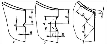
Picture 5 – Types of damage to edges, tops (end portions) of blades and their characteristics [11].
(a – nick: (typical sizes) А – nick length; Б – nick depth, measured along the chord structure; В – distance from the peripheral end of the scapula to the middle of nick.
б – dent: А – dent length, measured along the front edge of the blade; Б – maximum depth of indentations (measured in the plane perpendicular to the profile of the blade front edge); В – distance from the peripheral end of the scapula to the middle of bruising (measured along the front edge of the blade); Г – maximum width of indentations (measured on the surface of the profile from the back or the front edge of the trough perpendicular to the blade).
в – curvature: А – magnitude of the bent part of the blade profile, measured along the input (output) edge; Б – the deviation of the vertex of the scapula; В – magnitude of the bent part of the blade profile, as measured by the peripheral edge of the blade)
Damage to the blades in operation are random in appearance as the damage and injury on the distribution of the pen blades.
The distortion of the calculated geometry of the damaged rotor blades causing imbalances and increased vibration motor, and can also cause the appearance of new modes and resonant oscillations of blades. The most dangerous bending vibrations of the first forms (pic. 6) [11].
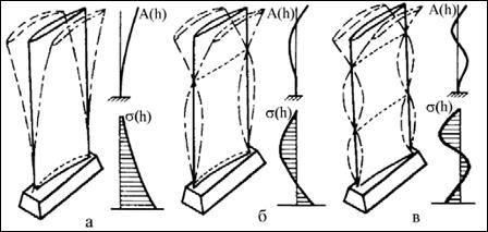
Picture 6 – Forms of flexural vibrations of rotor blades and the distribution of displacement amplitudes А(h) and stress sigma(h) [15]: a – first (1X1), б – second (2X1), в – third (3X1) form.
Thus, in general, the causes of the loss of turbine blades can be [11]:
- reduction in fatigue limit due to the formation of microcracks in the surface layer damaged by machining unregulated;
- increase in the amplitude of vibration stress due razzazorivaniya shelves due to wear bandage contact pads;
- inconsistency of shroud flange tightness specifications in the assembly;
- overheating due to uneven temperature field in front of the turbine;
- breach of duty;
- lack of cooling system efficiency;
- increase in the amplitude of vibration stress due to changes in excitation conditions (burnout nozzle vanes apparatus, coking fuel injectors, etc.);
- uneven distribution of load on the teeth of the shank;
- non-optimal cutting data profile shank;
- inadequate processes stamping, heat treatment and molding blades, etc.
In the analysis of damage to rotor blades of turbines due to thermal fatigue and to develop ways to reduce it in the general case should be considered [11]:
- at the same temperature gradient edges and the middle of the blade edges of the voltage is always greater than in the middle;
- when you start the engine in the edges arise compressive stresses that can, in some cases, cause a loss of stability;
- when stopping the engine on the edges of the tensile stresses occur the greater the higher the mode, from which is off;
- with a significant temperature gradient arising from thermal stresses may exceed the elastic limit and repeated many times can cause damage (formation of cracks), the type of low-cycle fatigue;
- mvelichinu stress can be reduced by lowering the temperature gradient due to a smoother increase of the fuel at startup, the engine cooling for reduced mode before shutting down, and a number of constructive measures (edge film cooling, thermal insulation on the edges of the gas flow, the use of uncooled hollow blades).
Depending on the choice of material and the cyclic durability of coatings can be increased up to 10 times due to higher ductility of the material.
4.3 The existing technology of repair and restoration of GTE blades
At present, there are many technologies for repair and restoration of GTE blades. The development of science and technology at a rapid pace, reveals to us a number of technologies aimed at reducing costs and increasing the quality of repair and restoration of GTE blades.
The technology of repair and restoration of GTE blades consists of phases:
- input control;
- metallurgical research;
- removal of external and internal heat-resistant coating;
- surfacing;
- heat treatment;
- preparation of a coating;
- coating on the inner cavity;
- coating on the flow part of the blade;
- to control the output.
Consider some of the methods of surfacing:
Electron-beam welding.
Recent innovation in the repair and restoration of GTE blades used electron-beam welding. Technology and equipment are designed for application in a vacuum gradient of powder coatings of significant thickness (up to 15 mm) in order to increase the surface strength, wear resistance, corrosion resistance, thermal resistance and modification of other physical, chemical and mechanical properties of the surface layers of materials and products from them [17].
Plasma-spraying surfacing.
Currently, among the methods of powder plasma surfacing is the most common method, which uses compressed straight arc burning between the electrode and the workpiece. At the same time abroad, the most widely used method for powder plasma surfacing, called the RTA – the process (plasma transferred arc). With this method, there are both primary arc (burning between the electrode and the workpiece) and the indirect or the pilot arc (burning inside the torch between the electrode and the plasma-forming nozzle). Due to the fact that the coating process only indirectly called plasma arc plasma deposition, a new technology called plasma-deposition welding [16].
Pulsed-laser cladding.
The developed technology for restoration of worn blades by pulsed laser deposition can largely eliminate the shortcomings of the existing technology of repair blades by arc welding (pic. 7) and a significant economic effect by reducing the complexity of the repair and improve the service life of blades:
- Significantly reduce the amount of performance machining of blades, after surfacing, as allowances for subsequent machining after welding shall not exceed 100 microns and virtually located in the geometric tolerance zone after welding.
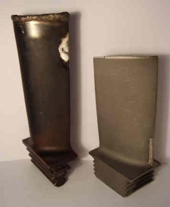
Picture 7 – Recovery Methods blades arc welding and pulsed laser deposition, respectively [18]
- Eliminate the heat treatment process steps before welding and after welding blades, as the heat affected zone are at the level of hundreds of microns.
- In the deposited layer forms a fine structure, providing increased wear resistance of the surface layer to the level of new blades and more.
- Allows you to extend the zone of repair of blades due to the minimum heat-affected zone, compared to the arc welding with a third of the height to 100%, that is, before fastening the scapula area.
Pulsed laser deposition technique opens up new potential for the repair of blades and allows you to:
- Eliminate time-consuming process steps for removing and installing the blades of the turbine shaft with a drive to send them to the repair factory, that is, to repair immediately to the gas-pumping station.
- Create a mobile system for repair of blades, allowing repair of blades directly to the gas-pumping station.
Pulsed laser deposition technique can be used to restore worn-out blades of aircraft turbines, nuclear, thermal and hydroelectric power plants [18].
During the implementation of Masters will be the method of vacuum ion-plasma coating technology in the laboratories of the Department of Mechanical Engineering at the facility Булат-6
(pic. 8).
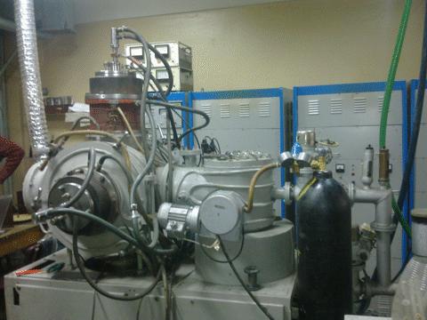
Picture 8 – Device for applying a vacuum ion-plasma coating Булат-6
Hardening is carried out by hardfacing vacuum-arc method CIB without the ion beam, or assisting with the high-energy (20 – 150 keV) ion beam, as well as through polienergeticheskoy implanted metal ions with energies up to 150 keV. Improvements decorative properties is due to deposition of decorative coatings[19].
An example of GTE blades after the application of vacuum ion-plasma coatings.
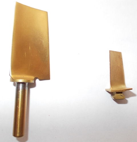
Picture 9 – Rotary vane and working with the application of vacuum ion-plasma spraying
Findings
In this paper we analyzed the current status of the issue, maintenance and repair of blades of gas turbine engine TW3–117. The existing methods of repair and restoration of GTE blades, examined the work and the design features of CCD TW3–117, also analyzed the types of damage to the compressor blades and turbine blades.
There are a lot of technology of repair of GTE blades, which have their advantages and disadvantages. But science is developing, so you need to use more advanced technologies that will reduce costs and improve reliability, durability and abrasion resistance of GTE blades. These technologies are the compositional techniques that are based on the composition of the main features and principles of the synthesis of composite and functionally-oriented technologies.
In writing this essay master's work is not finished yet. Final completion: December 2012 Full text of the work and materials on the subject may be obtained from the author or his head after that date.
List of sources
- Казаков Роман Александрович ОАО
НПО Сатурн
УГ Мет, Конструкторско-технологическое бюро перспективного развития, г. Рыбинск,Изготовление лопатки ВНА компрессора ГТД изотермической штамповкой
. - Крымов В.В., Елисеев Ю.С., Зудин К.И.
Производство газотурбинных двигателей
/ Под ред. В.В. Крымова. М.: Машиностроение / Машиностроение – Полет, 2002. – 376 с., ил. - Технологическое обеспечение эксплутационных характеристик деталей ГТД: монография / Лопатки компрессора и вентилятора / [Богуслаев В.А., Муравченко Ф.М., Жеманюк П.Д. и др.]. – Запорожье: ОАО
Мотор Сич
, 2003. – 396 с. - А.Н. Михайлов, Е.А. Михайлов, Д.А. Михайлов
Основы синтеза композиционных технологий машиностроения
. - Михаил Саркисов, Александр Саркисов, Данила Изотов
Жизнь семейства ТВ3–117
, ГУПЗавод им. В.Я. Климова
. - Богуслаев В.А.
Двигатель для воздушных трасс будущего
// Двигатель. – 2000. – №2 – 4. - Петр Изотов, Данила Изотов
Семейство ТВ3–117
, ГУПЗавод им. В.Я. Климова
. - Авиационная энциклопедия
Уголок неба
[электронный ресурс]. – Режим доступа: http://www.airwar.ru/... - Свободная энциклопедия
Википедия
[электронный ресурс]. – Режим доступа: http://www.ru.wikipedia.org/... - Авиасловарь [электронный ресурс]. – Режим доступа: http://www.aviaslovar.ru/...
Рабочие лопатки авиационных ГТД. Часть 1. Эксплутационная повреждаемость рабочих лопаток
, Московский государственный университет гражданской авиации.- Летная школа
Капитан Нестеров
[электронный ресурс]. – Режим доступа: http://www.flyingschool.ru/... - Справочник
АвиаПОРТ
[электронный ресурс]. – Режим доступа: http://www.aviaport.ru/... - Устройство автомобиля [электронный ресурс]. – Режим доступа: http://www.astra-world.ru/...
- Лозицкий Л.П. и др.
Конструкция и прочность авиационных деталей
. – М: Воздушный транспорт, 1992. – 535 с. - Научно-производственная фирма
Плазмацентр
[электронный ресурс]. – Режим доступа: http://www.plasmacentre.ru/... - Солдатов Анатолий Николаевич
Электронно-лучевая наплавка износостойких покрытий
. - Вятское машиностроительное предприятие
Лазерная техника и технологии
[электронный ресурс]. – Режим доступа: http://www.techlaser.kirov.ru/... - Научно-производственное предприятие
Булат
[электронный ресурс]. – Режим доступа: http://www.bulatsteel.ru/...