
Abstract
Contens
- Introdution
- 1 Cutoff of slag is problem at production of steel from the converter and ways of its decision
- 2 Analyses of designes of manypulators
- 3 Development of the design of the universal manipulator
- Conclusion
- References
Introdution
Now the priority direction in development of steel-smelting production is development of new technologies and the equipment which could provide higher quality and lower prime cost of let-out steel products. Properties of melted metal in many respects depend on applied technology at the final stages of process of production of steel which extra modular processing and a pouring concern became. As practice showed, efficiency of operations on the ladle furnace installations considerably is determined by steel refinement by amount of the final technological slag getting to a ladle during production of metal from the melting unit. Especially sharply the problem of the high-oxidized slag is shown in steel conditions of production in the oxygen converter. For this reason still development of perfect designs of manipulators for input of gate-type elements in a final opening of the oxygen converter doesn't lose the urgency.
For realization of release began to use expediently without slag locking element in the form of a float which floats on border of division of the slag-steel
environment and in the course of the expiration of steel corks with itself a final opening of the converter, thereby cutting slag. For input of a gate-type element in the converter it is supposed to use the electro pneumatic manipulator.
1 Cutoff of slag is problem at production of steel from the converter and ways of its decision
Now the simplest way of a cutoff of slag in converter’s shops is its deduction by a way of fast transfer of the converter in vertical situation [1]. However this way in real working conditions doesn't give necessary degree of a cutoff because of a changing configuration of the final channel which forms a leaving stream. The operator visually supervises the moment of emergence of slag in a stream of metal and expiration process of melt (fig. 1).
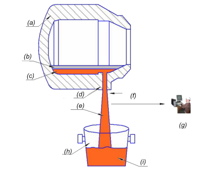
Figure 1 – The scheme of realization of visual control of the beginning of the expiration of slag from the oxygen converter in a ladle: (a) – converter; (b) – slag; (c) – steel; (d) – final opening; (e) – steel stream; (f) – visual control; (g) – operator; (h) – steel-ladle; (i) – steel
The main lack of this way is existence of the rest of metal in the converter that leads to decrease in its productivity, violation of thermal balance of melting and stability of a purge, also partial exit of slag with steel in a ladle. Besides, in the course of release in a zone of an opening there is a vorticose movement of metal and slag which tightens the last in a stream, and the end result of release directly depends on qualification of the operator. All this doesn't give possibility reliably to separate metal from slag and consequently now the greatest application was received by such ways of prevention of hit of slag in a ladle as:
- gasdynamic way (fig. 2) assuming influence by a gas stream on a stream melt in the final channel of the converter of submitted under superfluous pressure by means of a nozzle, built in the locking element fixed on the rotary lever, a power air actuator put in action [2].
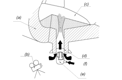
Figure 2 – Gasdynamic way of a cutoff of converter’s slag power air actuator: (a) – converter; (b) – system of detection of slag; (c) – liquid bath; (d) – final opening; (e) – lock nozzle; (f) – gas
- the way with use of a sliding-vane lock (fig. 3) which establish on the final canal outside of the converter and at the moment of emergence of particles of slag in a stream of production of metal this lock blocks the converter channel a fire-resistant plate which moves by means of an electromechanical or hydraulic drive [4]. A signal to overlapping of the target channel and start of a drive is the team arriving from a radiating pyrometer;
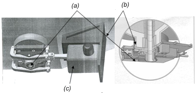
Figure 3 – The placement scheme on the case of the converter of the sliding-vane locks used for an cutoff of slag: (a) – lock; (b) – converter; (c) – lock drive
- a way based on application of special gate-type elements such as a float (fig. 4) which are made of a fire-resistant material and are located in a converter bath by means of the special devices blocking an entrance opening of the channel at an approach of a layer of slag to it at a final stage of production of metal.
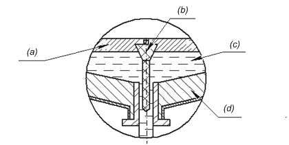
Figure 4 – Way of a cutoff of slag with use of elements such as a float:
(a) – slag; (b) – gate-type element; (c) – steel; (d) – converter
Slag keeps in the converter at the expense of a dynamic pressure of the gas blown through a stopper into a final opening. The case of a stopper is made of cast iron, in its center the nozzle opening through which on a signal the compressed air or nitrogen moves is executed. The size of a stopper should be such that between its external surface and internal walls of a final opening there was a ring-shaped gap through which there could be an air submitted for deduction of slag in the converter. The team arriving from a radiating pyrometer, a radiation level registering on change the completion of passing through a final opening of metal and the beginning of a descent of slag is a signal to the beginning of supply of the compressed air (nitrogen) and moving of a stopper [3];
Cutoff of slag by means of the gate-type elements entered into a bath of the converter, is the most widespread way that is caused it by simplicity and reliability in comparison with the ways described above. Advantages of this way: all elements are out of a zone of influence of high temperatures, and the most loaded element under the influence of temperature is the bar entered into a cavity of the converter, for the period of no more than 30 with; lack of need of use of expensive systems of early detection of slag in a stream of let-out steel; a convenient arrangement of the device on a working platform [5].
2 Analyses of designes of manypulators
Special devices for input of gate-type elements such as a float in a cavity of the melting unit at a final stage of production of steel from it are called as manipulators. The handling systems intended for input of gate-type elements in a bath of the oxygen converter, should meet the following requirements:
- compactness of a design in non-working situation and possibility of its placement in the taken-away place on a working platform at the converter;
- sufficient accuracy of positioning of a gate-type element concerning an axis of the final channel of the steel-smelting unit before dumping;
- high reliability of work in the conditions of intensive thermal influence and a high dust content;
- possibilities of automatic providing the set trajectory of movement of a gate-type element at input in the converter without considerable complication of a control system by drives [5].
The manipulators used at the modern metallurgical enterprises, happen two types:
- Suspended type (fig. 5) representing lever system in the form of a parallelogram put in action pneumatic cylinders and fixed on arms over a working platform.
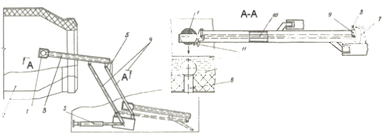
Figure 5 – The manipulator suspended type: 1 – bowl-tube; 2 – converter; 3 – a hollow rod; 4 – levers; 5 – cylinder; 6 – outlet; 7 – emphasis; 8 – ledge; 9 – link; 10 – longitudinal rod; 11 – dog.
- Floor manipulators, which can be mobile or stationary. In fig. 6 shows a mobile crane type rail, which is a self-propelled truck with lifting mechanism and turning the rod carrying the cutoff element [6].
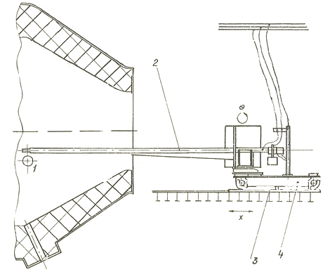
Figure 6 – The manipulator rail types: 1 – a ball–stopper, 2 – rod, 3 – railroads, 4 – self-propelled trolley.
Thanks to the folding mechanism in the neutral position takes up little space, but its repair and maintenance of certain difficulties arise due to the fact that he is out of range of crane equipment [5].
The advantage of such a manipulator in the simplicity and reliability, but it takes a lot of space on the site and requires access roads to impede the work of machines for relining converter.
The most successful designs of stationary manipulators should be considered as a system, developed by Monocon
[7-9].
Manipulator of telescopic type (fig. 7) is a structure installed permanently on site.
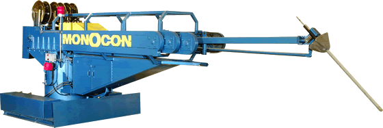
Figure 7 – The manipulator of telescopic type
The disadvantages of this design is the low reliability of the devices in the work because of the high probability of jamming of the hollow rod, which is set to telescopically movable component, due to the warping of the bar under the influence of high temperatures while in the working space of the converter.
Manipulator with a lateral position with respect to the axis of the converter is shown in fig. 8. This manipulator is placed on site at the side of the oxygen converter steel production.
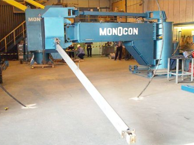
Figure 8 – The manipulator with side relative to the converter
The disadvantage of this manipulator – synchronous operation of two drives to provide the necessary shut-off element trajectory during its entry into the working space converter, which requires a special skill of the operator or the application of expensive automatic control system.
Manipulator with coaxial position with respect to the axis of the converter (fig. 9). The disadvantages of this design the robot arm are: the presence of an auxiliary track on-site and large size, which limits its use in the absence of free space in the working area [5].
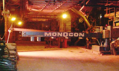
Figure 9 – The manipulator with coaxial position with respect to the axis of the converter
Employees of the department MOZCHM GVUZ Donetsk National Technical University
was designed and patented by the manipulator, in which the developers have managed to some extent, eliminate the disadvantages inherent in the manipulators discussed above floor type. Schematically it is shown in Figure 10. The relations of structural elements bevel gear manipulation system can automatically provide the same time when you turn the string to the console at an angle of 90 degrees, from its initial position relative rotation of the bracket at 180 deg., resulting in the console and bracket will be oriented in a coaxial line and take the position of the oxygen converter kick shown in figure 10, b. Subsequent delivery shut-off element in the zone the outlet channel converter (see figure 10, c) the moving carriage with a hollow rod with respect to the bracket using the rope drive [9-11].
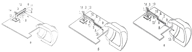
Figure 10 – Installation of the manipulator and the axial arrangement of its elements in the source (a), intermediate (б) and final (в) The provisions of the: 1 – a vertical column; 2, 3 – upper and lower fixed bearing supports; 4 – management; 5 – bearing assembly, vertical shaft; 6 and 7 – an arm, having two longitudinal guides, which are located in the carriage rollers; 8 – carriage; 9 – hollow bar; 10 – shut-off element; 11 – bevel gear pair; 12 – horizontal shaft; 13 – bevel gear; 14 – bevel gear shaft-pinion.
In fig. 11 shows the construction of a lateral arm type developed by the staff GVUZ Donetsk National Technical University
in cooperation with specialists from the NPO Donix
[9-11]. Owing to the peculiarities of the kinematic scheme, bracket 9 can be rotated on the vertical axis in the horizontal plane relative to the console when it is rotated 90о with the column at an angle 180о, which eventually provides the desired trajectory of the shut–off element and its clear orientation about the axis of the outlet channel of the oxygen converter without the use of sophisticated and expensive systems for controlling the drive, which includes only one motor.
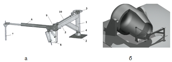
Figure 11 – Three-dimensional model of the manipulator (a) and its position at the time of discharge shut-off element (б): 1 – a vertical column; 2, 3 – fixed support; 4 – toothed wheel; 5 – console; 6 – hollow bar; 7 – shut-off element; 8 – engine balancing rod; 9 – bracket; 10 – traction.
This manipulator places on a working platform sideways the oxygen converter from production of steel. Thus it in starting (non-working) position doesn't interfere with work installation for drawing by spraying of a semi-fluid material on a unit surface and devices for the mechanized destruction of a worn-out lining. The design of the manipulator can change the departure hollow rod that makes pre-setting mechanism to ensure alignment with the longitudinal axis of the outlet channel converter guide rod shut-off element at the time of discharge into the molten metal in the final stages of the process of tapping [11].
The disadvantages of this manipulation of the system include the fact that the presence in the shop shielding from thermal radiation to be placed at the side of the BOF, the system manipulator cannot be used to implement the cutoff final slag.
Based on the results of the analysis of the existing structures of manipulators can be concluded that these variations due to the specific location of the main and auxiliary equipment in the offices of converter smelting shops of domestic steel producers. On the working area near the BOF to efficiently accommodate multiple machines, each designed to perform a strictly technological or repair operations. Thus all known systems of processing special.
3 Development of the design of the universal manipulator
In the development of advanced design system manipulation task was to create a universal machine that could be utilized for the implementation of several (at least two) operations associated with providing relief shutoff element in the oxygen converter bath, as well as with the installation of the shield used during the repair of the neck outlet channel and the elements melting furnace refractory lining. As a prototype design of the robot arm used a lateral type.
The construction of the universal manipulation system is shown in figure 12.

Figure 12 – The proposed handling system: a – a front view, б – lateral view, в – view from above
In the universal manipulation system includes a vertical column, installed in the fixed support 2, 3 and 4 equipped with a turning mechanism that transmits torque through its gear 5, column 6 is rigidly fixed boom, which will be designed metal shield, so necessary for repair of the converter which is cinematically linked to the hollow rod 7. This bar has the ability to rotate in the vertical and horizontal planes, equipped with a balancing mechanism, which includes a pneumatic power, and carries on the front end of the shut-off element 8, held by a spring-loaded latch. Go to the bottom of the fixed bearing two columns with a finger attached to one end of the rod 10, a second end which is pivotally connected to bracket 9. Owing to the peculiarities of the kinematic scheme, this bracket can be rotated on the vertical axis in the horizontal plane relative to the boom 6 to 90о when it is rotated together with the column at an angle of 180о, which eventually provides the desired trajectory of the shut-off element and its clear orientation about the axis of the outlet channel BOF without the use of sophisticated and expensive systems for controlling the drive, which includes only one motor.
This handling system will allow more efficient use of space around the converter and run if necessary, two important functions:
- Entering into a bath converter shut-off elements in it to keep the final slag;
- Install a protective screen in front of the neck converter located in a horizontal position for carrying out repairs.
Conclusion
In the master's work was an analysis of existing devices to cut off the slag during pouring of steel from the BOF to identify their strengths and weaknesses, as well as decisions taken in their structures associated with the specific conditions of operation of the equipment. Based on the analysis of design such as a sidearm to enter the shut-off elements in the outlet of the oxygen converter and perform repairs to his neck, vent channel, and the refractory lining in Yenakiyevo Steel.
When writing this paper the master's thesis wasn't complete yet. The full text of work and materials on a subject can be received at the author or his research supervisor after January 31, 2013.
Referenses
- Штилькеринг Б. Эффективнось методов отсечки шлака при сливе металла из конвертера/Б.Штилькеринг//Металлургия и горно-рудная промышленность. – 2002. – № 10 – с.38-41.
- Пат. 2070578 Россия, МКИ С 21 С5/46, F27 D3/15. Устройство для отсечки шлака при выпуске металла из конвертера/ Г.Н. Ролдугин, Н.В. Сафонов, Д.В. Захаров, и др.: Заявл. 14.03.1994; №94009052/02; опубл. 27.10.1995.
- Кудрин В.А. Металлургия стали. Учебник для вузов/В.А.Кудрин – 2-е изд., перераб. И доп. – М.: Металлургия, 1989. – 560 с.
- Греф У. Бесшлаковый выпуск плавки с помощью затвора выпускного отверстия ТАР 120 при производстве чистой стали /У.Греф, А.Бергховер, Г. Амелер, и др.//Сталь. – 2005. – №7. – с.51-54.
- Бедарев С.А. Обоснование параметров и усовершенствование системы отсечки конвертерного шлака элементами поплавкового типа при выпуске стали. Дисс., к.т.н. – Донецк: ДонНТУ, 2011.
- IFGL Refractories Ltd.
- Monocon International Refractories
- Еронько С.П. Разработка эффективных схем отсечки шлака при сливе металла из конвертера/С.П.Еронько, А.Н.Смирнов, Д.П. Кукуй//Металлургическая и горнорудная промышленность. – 2003. – №8. – с.33-37.
- Использование математического моделирования и САПР при разработке устройства для отсечки конвертерного шлака/С.П.Еронько, Е.В.Ошовская, В.В.Киселев и др.//Международный сборник научных трудов
Прогрессивные технологии и системы машиностроения
. – Донецк: ДонГТУ, 2002. – Вып.23. – с.52-56. - Пат. 71681 UA, C21 C/46. Пристрій для відсічення шлаку при випуску сталі з конвертора/С.П.Єронько, О.М.Смірнов, О.Ю.Цупрун та інш.: Заяв. 20.04.2004; опубл. 15.12.2004, №12.
- Белянин П.Н. Промышленные роботы/П.Н Белянин. – М.: Машиностроение, 1975. – 400с.