
Abstract
Content
- Introduction
- 1. Sinter production
- 2. Analysis of existing structures crushers
- 3. Description of proposed construction roll crushers
- 4. Desing of crushing process
- Conclusions
- References
Introduction
Sinter production is one of the early stages of the metallurgical cycle. The result is the production of sintered agglomerate, which is acharge, which consists of: iron ore, coke fines (particle size less than 3 mm), culm (3 mm), thin coal (up to 3 mm), limestone (up to 3 mm), lime and return (defective fine agglomerate sizes up to 5 mm, returned to the charge for the re-sintering) [1].
Sintering of agglomerate in special sintering machines that issue in the form of sinter cake. Obviously, the continued use of sinter in this form is impossible. For this purpose, immediately after the sintering machines, install crushing equipment, which crushes the sinter cake to the desired size. In most cases, this function is carried out crusher, which allow to obtain a high uniformity of particle size output. Crushers may have different design and implement various ways of breaking the agglomerate. This paper will provide an overview of sinter production, the analysis of existing designs crushers, andstudied in detail the design features single roller gear grinders.
1. Sinter production
Sinter plants are usually placed directly on the steel mills. This is due to the need to use in the production of sinter a large amount of by products and wastes of metallurgical production, as well as the complexity of the transportation of the finished sinter.
Sinter, fluxed especially when transported over long distances and congestion collapses, resulting in a significant number of sub-standard stuff. The location near the blast furnace sinter plant enables the transport of sinter belt conveyors.
Figure 1 shows a circuit diagram of apparatus sinter plant with astraight-line conveyor machine and sinter cooler.
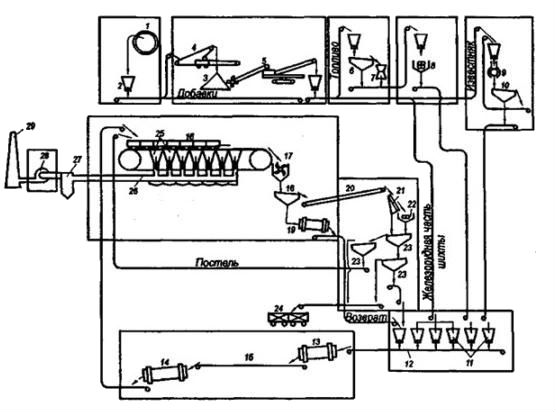
Figure 1 – Layout of equipment for sintering factory
Charge materials arriving at the sinter plant by rail, rotary car dumper unloaded in a receiving hopper 2. Before the rail car dumperi nstalled scales for weighing incoming raw materials. In the distant transportation of Sintered Ore and concentrates with natural moisturein the winter freeze together. This leads to a complication of handling and additional costs for construction and operation of garages thawing.
In the blending stock material are stacked in piles 3 and continuous layering which the conveyor belt 4, hopper trucks and stackers.
From the stacks of raw materials in various ways, such as bucket wheel excavators 5 is loaded on the outlet conveyor belts and transported to the Department of charge bins. Loading conveyor system stack, the existing sinter plants at home, do not provide the desired uniformity of raw materials.
Limestone is used for grinding hammer mills such as DMRIE 9 operating in closed circuit with screens 10. Sometimes the limestoneis ground in two stages: in the hammer mill to a particle size 8-0 mm and ball mills to a particle size less than 3 mm [6].
Fuel (coke) depending on the size of the original ground in one or two stages. In the latter case, the first stage of crushing to a particle size 15-0 mm conecrushers 7 used types of KMD-1750 and KMD-220.
Cox to crusher hits the slow rumbling 6, where the fine fraction is eliminated, and then after crushing screened out along with the trifle is served in four roller crusher 8 on the second stage of milling. In single-stage grinding roller mills use only.
All charge materials, prepared for the size distribution, enter the charge separation bins. 11 bins with a capacity of 70-100 m3 have rows, the number of rows corresponds to the number of sintering machines at the factory.
Loading bins charge is a conveyor belt equipped with dropping drum trolleys or mobile conveyor. The components of the sinter mixture discharged from the bunkers, or poppet elektrovibrating feeders pass through a system of automatic weighing and dispensing, are placed on a conveyor belt assembly 12 and are directed into the body of the primary mixing.
Perhaps the mixing and pelletizing in one unit – mixer-pelletizers. When you boot into the intermediate hopper there is a segregation of the charge, worsening the agreement reached by the uniformity of size. With this in mind, the modern large sinter plants tend to exclude the intermediate hopper and charge of the drum mixer 13 in 14 pelletizers transfer conveyor belt 15.
The prepared blend of pelletizers or secondary mixer is loaded on the tape shuttle dispenser that fits evenly into the hopper feeder drum batch sintering machine 16. Before loading the burden on the moving grate trolleys fit a protective layer of the bed – agglomerate particle size of 12-25 mm. Loaded trucks come under the fiery furnace, where there is inflammation of the upper layer of solid fuel mixture. With further progress on the trolley through a layer of sinter blend penetrate air and burning fuel from the upper layers are gradually moved to the bottom. After sintering, sinter made in the tail of the sinter descends from carts and comes in a single roller crusher gear 17, and from there to roar samobalansny 18, where stands the hot return (6-0 mm fines); oversize product is fed to the cooler 20.
For the first stage of screening to secondary fragmentation are widely used stationary screens 21, separating the agglomerates into two classes. Oversize product is subjected to grinding in a double roller crusher 22. At later stages of screening on the screens like 23, agglomerate is separated into a product fit and returns, and stands for the sinter litter layer applied to the grate carts.
After sorting conditioned sinter belts is sent to the blast furnace shop, or loaded into special railroad cars 24.
Hot gases obtained during the sintering agglomerate, sucked supercharger (exhauster) 28 through the vacuum chamber 25, the gas reservoir 26, de-dusting system 27 and are released into the chimney 29 [2].
2. Analysis of existing structures crushers
As noted earlier, one of the most important technological operations sinter production process is its fragmentation after the disappearance of a trolley car.This operation is performed using special shears.
The most common types of crushers are:
–cone;
–jaw crusher;
–roll;
–hammer.
Crushing device shown in Figure 2. The destruction of these pieces of ore occurs as a result of crush, split, abrasive effort and strokes. In black metal jaw crusher material injected into the crusher from the top, crushed rocker 2 and a fixed cheeks, and the cone crusher maximum coolies 12 fixed and 13 rotating inner cones.
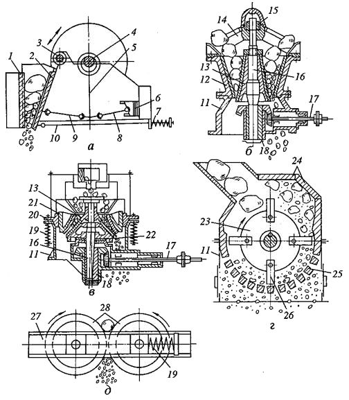
Figure 2 – The design scheme of crushers:
a – jaw, b – cone, c – mushroom, d – hammer, e – roller;
1 – fixed cheek with the rotation axis; 2 – a movable cheek; 3, 4 – the eccentric shaft; 5 – rod; 6 – hinged rear bearing spacer cheeks; 7 – spring; 8, 9 – width adjustment mechanism of the discharge gap; 10 – pull the lock device; 11 – bed; 12 – still cone; 13 – cone moving; 14 – traverse; 15 – hinge suspension rolling cone; 16 – cone of the shaft; 17 – drive shaft; 18 – eccentric; 19 – amortization spring; 20 – foot ring ;21 – regulating ring; 22 – thrust bearing cone; 23 – rotor; 24 – linerplates; 25 – grate; 26 – hammer; 27 – main frame; 28 – crushing rolls.
Shaft 13 includes a cone in a rotating cam 18. In the jaw crusher is only one course of movable cheek is working, during the reverse part of the cheeks of crushed material has time to get out of working space through the bottom of the crusher outlet slit.
The performance of the largest jaw crusher does not exceed 450-500 t/h. Characteristic cases of jaw crushers are pressing the working space during the fragmentation of wet clay ores. In addition, jaw crushers should not be used for crushing ore with platy structure of a piece of shale, as individual tiles in the case of the orientation of their long axis along the axis of the slit issuance of crushed material can pass through the crusher working space without being destroyed.
Cone crushers can be successfully used for the ore of any type, including with a layered (platy) the structure of the piece, as well asclay ores. Cone crushers do not need feeders and can operate under the rubble
, its mean, the working space is completely filled with ore coming from the hopper above it.
In the cone crusher the axis of rotation of the inner cone does not coincide with the geometrical axis of the fixed cone, its mean, at any time ragging going on in the area approaching the inner and outer surfaces of the fixed cones. In the remaining areas are crushed product delivery through the annular gap between the cones. Thus ragging in the cone crusher is carried out continuously. Achievable performance is 3500-4000 t/ h (i=3-8) at a flow of electricity to the fragmentation of 1 ton of ore 0,1-1,3 kWh.
In the hammer mill crushing ore is mainly under the influence of impacts on them of steel hammers mounted on a rapidly rotating shaft. In the steel mills in the crushed limestone crushers, used later in the sinter plants. Brittle materials (example, coke) can be crushed in roll crushers.
Roller crusher set immediately after the unloading part of the sinter. The device, removing the cake from the sinter machine carts may bestationary or mobile. Efficient mobile performance, ensuring the regulation of clearance between the grate carts and removable tines of screening devices. The regulation is performed during installation, repairs and depreciation, as the teeth.
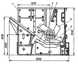
Figure 3 – Typical design of single roller toothed crusher:
1–case; 2–the rotor shaft; 3–wear plate; 4–toothed sprocket rotor; 5–grate.
Crusher, in addition to meeting the basic problem of crushing, is both a feeder for the set of her hot sinter screen to protect from shock and roar of heavy pieces of sinter.
In “Severstal” (Russia) Lump applied toothed crusher (Fig. 4). Grate based on box-type girder, placed parallel to the roller with teeth, and fixed on the beam with a given step through the U – shaped plates and stops at the rear. The length of the working surfaces of grate, roll under the teeth, reduced to the lowest possible value, which dramatically reduces the thermal deformation of the hot grate for crushing materials.
a
b
Figure 4 – Crusher designSeverstal
а–front view, b–top view.
If you wear a working part of the grate and use them to turn over again. To capture the grate ,when turning the slings and replacing each of them has two grooves. P plate – shaped, located between the grates, forming a step between the grate and close the gap between them to avoid getting into a zone of lower tonnages of material, located behind the grate. [4].
3. Description of proposed construction roll crushers
From a review of the design of crushers that Double roller crusher for crushing sinter in steel companies are not used, but their implementation involves significant additional costs. In the effective destruction of the jaw crusher sinter cake can not be achieved from a high temperature, while the energy is lost in the elastic deformation of the agglomerate.
In this regard, Single roller gear grinders are more promising, as were widespread, and the destruction of the pie of aglomerate occurs mainly by punching (cut) through the grate, which is less energy-consuming compared to crushing in jaw crusher. Therefore, improving the design of single roller gear grinders to overcome weaknesses is an important practical challenge for professionals designing organizations [4].
Figure 5 shows the proposed kinematics single roller crusher gear, which used an additional grate, which offers a two-stage crushing process, which provides a high homogeneity of the resulting lumpsinter.
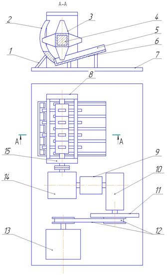
Figure 5 – Kinematic model of single roller toothed crusher:
1 – support the vertical grate; 2 – grate of the second stage of crushing; 3 – star; 4 – rotor; 5,6 – grate of the first stage of crushing; 7 – the foundation of the crusher; 8 – reference node (plain bearing); 9 – tensoresistance sensor; 10 – a cylindrical double reduction; 11 – flywheel; 12 – belt drive; 13 – electric; 14 – worm gear; 15 – elastic coupling bush-finger.
In addition, the added drive belt transmission, which will prevent its failure in case of jamming gear roll.
On the motor shaft 13 is rigidly fixed drive pulley belt transmission 12. Since the diameters of the pulleys are the same, the transmission ratio belt transmission ip=1. The second pulley with gear coupling is connected to the input shaft of a high-speed bevel-helical gear 10(i1=7,5). Between the two gearboxes is tensoresistance converter 9 which enables you to control the torque transmitted by low-speed reducer 14 (i2=11). The output shaft of the gearbox is connected to the rotor crusher four elastic bush-finger sleeve 15. Fragmentation of the sinter cake is on the grate 2 and 5, which have different gaps between the grates.
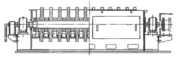
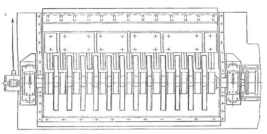
Figure 6 shows a drawing of single roller gear grinder (top view)
")
Figure 6 – Drawing of single roller gear grinder (top view)
4. Desing of crushing process
On the offered kinematics chart the physical model of one rolling toothed crusher was constructed in a scale 1:10 (figure 7). On this model experiments were conducted on growing of material shallow, which information allow to describe the real mode of work of crusher was certain during.
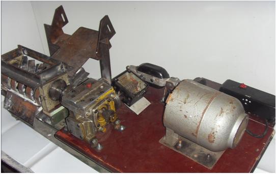
Figure 7 – Model of one rolling toothed crusher
The process of growing of material shallow on the physical model of the probed crusher flows in two stages. In the beginning array of material points of the revolved asterisks 3 raskalyvayut on large fragments, gettings on a pallet 6 sloping furnace-bar grate 5 and pushed from him in the area of location of cylindrical grate 2. Then appearing fragments go through the narrow openings of this grate, the pieces of the set size, which on sloping tray 1 are poured in receiving.
As material, imitating an agglomerate at the design of process of his crushing, it was decided to use penobeton and foam plastic, as on the complex of properties they in a most measure correspond the terms of experiment. During experimental researches of process of growing of material shallow the change of total moment of resistance the rotation of rotor of crusher was controlled. In the process of functioning of model of crusher there is an electric signal, acting from a transformer, after strengthening and transformation to the digital code on a computer under the management of the specialized software.
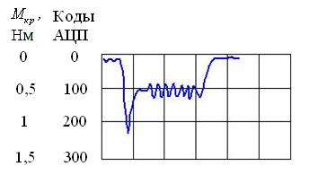
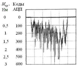
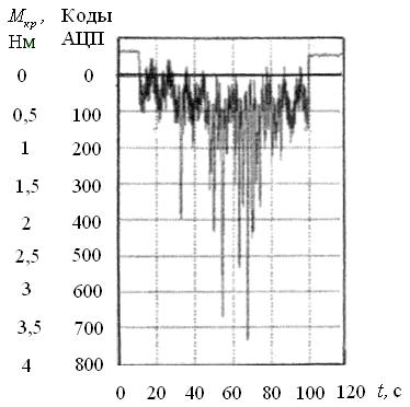
On a figure 8 the characteristic types of signals, registered at growing of penobetona shallow during control of twisting moment, transferrable a muff which linked the proper billows of high-speed and slow reducing gears of drive are rotined.
а
b
c
Figure 8 – The characteristic type of the registered signals at control of twisting moment, developed the drive of model of crusher during idling (a); at destruction of pieces on one (b) and simultaneously on two (c) grates.
As be obvious from the resulted charts, the drive of model of crusher is exposed to the action of peak-loads, caused brief, alternating in time reactive forces, arising up in the area of contact of heads of points of asterisks with the plate of material in the moment of its destruction on large fragments and subsequent their crushings of the to pieces required size. The indicated character of change of the technological loadings showed up for both types of material, used as an imitator of ground down agglomerate. Thus moment of idling and moments of resistance the rotation of rotor with asterisks, conditioned crushing of material on the first and second furnace-bar grates, made according to 10, 12; 60, 65 and 23, 30 % from the total value of twisting moment, developed the drive of model of crusher [5].
Thus, on the basis of the got results of design of work of the offered crusher, it is possible to draw conclusion about its capacity and possibility of its applying in industry.
Conclusions
The efficiency of the blast furnace is largely dependent on the quality of sinter, regulated, especially with the iron content of the fractional composition in the range 5 ... 50 mm. The presence of large pieces(> 50 mm) and dust inclusions (less than 5 mm) in the product sinter produced in Ukraine, due to imperfections in the factories operated by crushing equipment (jaw, single and double roller crushers gear).The proposed design will allow the crusher to get rid of this drawback, since it provides an increase in the proportion of sinter in the charge, the fractional composition of which is in the optimal range.
Now master's degree work is in the stage of writing, with an abstract in full it is possible bude to familiarize after 31.01.2012
References
- Вегман Е.Ф. Теория технология агломерации. М.– 1974
- Каталог производственного оборудования
Tehnoinfo.ru
[электронный источник]Tehnoinfo.ru
- Воскобойников В.Г. и др. Общая металлургия – 6-изд., перераб. и доп.– М.: ИКЦ
Академкнига
, 2005– 768 с. - Левченко О.А. Повышение эффективности дробления агломерата путем усовершенствования конструктивных параметров одновалковой зубчатой дробилки: дис.канд. техн. наук: 05.05.08 Левченко Оксана Александровна; Донбасс. гос. техн. ун-т.–Алчевск, 2009.– 176 с.
- Еронько С.П. Удинцев Р.А. Левченко О.А. Моделирование процесса измельчения материала на одновалковой зубчатой дробилке.– Металлургические процессы и оборудование.– 2012.– №1– с. 17-25.
- Патковский А.Б. Агломерационные фабрики черной металлургии. М.– 1954.
- Алтухов В.Н. Пути повышения эффективности дробления агломерата в одновалковой зубчатой дробилке / В.Н. Алтухов, О.А. Левченко // Разработка рудных месторождений : научно-технический сборник / КТУ.– Кривой Рог : КТУ, 2005.– Вып. 89.– С.151-154.