
Abstract
The content of the abstract
Introduction
The process of mine conveyor transport is a process moving rock mass, materials, and in some cases people through conveyors in mine workings. Conveyor lines with conveyor belts are mainly applied for the conveyor transportation in the mines. transport is mainly applied to the conveyor lines with conveyors. Modern underground conveyor lines are characterized by a significant extent (tens of kilometers) and branching transport routes that change over time, its parameters: the length, topology, etc.
One way to improve the efficiency of conveyor transport of coal companies is the use of automation systems.
1. Theme urgency
Studying of existing automation systems in purpose of identifying weaknesses and developing a number of activities and facilities to improve and enhance existing systems is an urgent task for today.
2. Goal and tasks of the research
The purpose of this work is improving the efficiency of the assembly line with intermediate hoppers by justification of the control method and the control algorithm, on which development of automatic control systems will be based.
To achieve this goal following tasks should be solved:
A. Analysis of the conveyor line with intermediate hoppers as an object of automatic control.
Two. Development of methods and mathematical models of the automatic control system for the conveyor lines with intermediate hoppers.
Three. Computer researching of mathematical models of the automatic control system for the conveyor line with intermediate hoppers.
Four. Circuit solution development for the automatic control system for the conveyor line with intermediate hoppers.
3. Results
As a result of analysis of automatic control methods was developed a new method of automatic control system for the conveyor lines with intermediate hoppers was developed, which could be achieved through the implementation of the three possible situations:
A. Normal operation. The mining combine works with a nominal feed rate and productivity Vnk, Qnk, conveyor operates at the rated speed with rated capacity of Vnkon and Qnkon respectively, hopper works in the transit mode, Wb = 0.
Two. Emergency operation (failure on the trunk conveyor and its stopping). In this case, we need to increase the cycle of the work by the time of filling the hopper tбзап. With support from the coordinating devices hopper is transferred to the accumulating mode, combine feed rate is reduced to V1k and thus performance is reduced to Q1k, conveyor speed is reduced to V1kon, capacity is increased to Q1kon; until the hopper will be filled completely (Wb = 1). Then the dispatcher of a coordinating device disables the processor, offloads conveyor, until the failure is corrected.
Three. The post-failure operation. The hopper is opened for the grant of the cargo on the main conveyor belt, conveyor belt starts running at speed V1kon and at the same time combine turns on with the processor speed of delivery and performance V1k and Q1k respectively. The area runs at these speeds for as long as Wb = 0, then translate the precinct on the processor pipeline and the rated speed Vnkon and Vnk respectively.
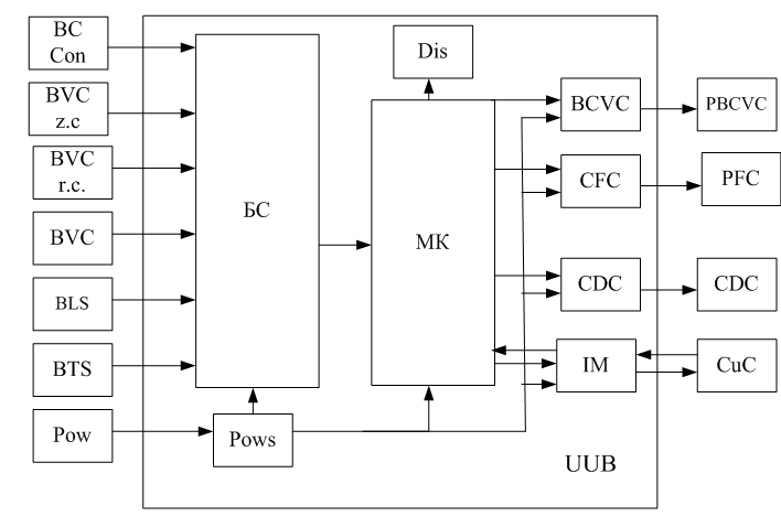
Hopper control device UUB was developed to implement the method of automatic control of conveyor lines with intermediate hoppers. Block diagram of the UUB device is presented in Figure 1.
Figure
1 – Block diagram of the control unit hopper
The scheme developed by the dotted line marked blocks.
In Figure 1, indicated by: BC Con – contact blocks of the control unit conveyor, БВК з.к. – Power on-off loading conveyor; BVC r.c. – Power on-off discharge conveyor, with a database; BLS – Block level sensors, БД п – Block of travel sensors, Pow – The power supply; БС – Block matching digital signals with a microcontroller, Pows – power supply unit; MK – Microcontroller; BCVC – Block matching with the winch starter, CFC – Coordination with the unit discharge conveyor, CDC – Coordination with the unit discharge conveyor, IM – Interface module, CuC – The control unit conveyor, Dis – scoreboard display.
The effectiveness of the
implementation of the solution for problem regulated
conveyor –
intermediate hopper
is
accomplished by increasing the time of the
operation. As known, the time of hopper filling with a nominal feed
rate Vnk, the nominal combine speed Vnkon and conveyor performance
Qnkon is determined from the relation:
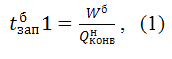
where Wb – the volume of the hopper, Qnkon – rated the performance of the conveyor.
After hopper transferring to the accumulating mode with support of coordinating unit, the feed rate is reduced to V1k and thus performance is reduced to Q1k, conveyor speed is reduced to V1kon, capacity increased to Q1kon. Time of hopper filling becomes equal to:
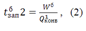
where Wb – the volume of the hopper, Q1kon – minimum performance of the conveyor.
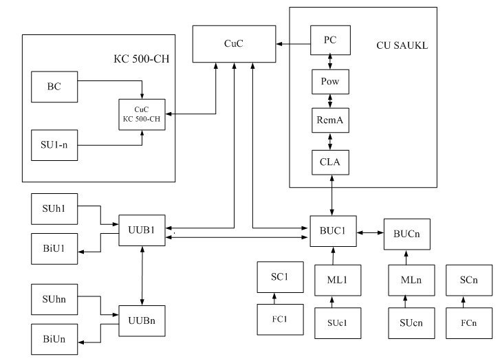
A block diagram of the automatic control system for the conveyor line with intermediate hoppers was developed on the basis of SAUKL, a complex of technical means of control shearer KC 500-CH, and control device designed hopper UUB, which is based on previous studies and presented in Figure 2. Figure 2 denotes a coordination device conveyor transport; BC – block actuators combine; SU1-n – sensor unit, CuC – coordinating unit, КС 500-CH – Control Unit combine; BUC1-BUCn – conveyor control unit number 1...n; SUc1-SUcn – sensor unit number 1...n; БДt1-БДtn – block conveyor sensor number 1...n; SC1-SCn – speed control device; FC1-FCn – frequency converter; CU SAUKL – remote control SAUKL; Pow – Uninterruptible Power Supply, CLA – communication line adapter; RemA – remote control adapter; UUB1-UUBn – device control bunker number 1...n.
Figure
2 – Block diagram of automatic control of conveyor lines with
intermediate hoppers
Conclusion
Block diagram, the hopper control unit and the method for automatic control system for the conveyor lines with intermediate hoppers using modern microprocessor technology were developed to improve the efficiency of the mine site.
Implementation of the proposed block diagram of an automatic control system for conveyor belts to the intermediate bunkers in the operating mode will adjust the feed rate and speed combine belt, in an emergency mode, use the storage capacity of the line in the post-fault to launch laden conveyor to provide not only a function of blocking and remote control, but also collect and process information from the associated equipment, transfer it to the surface for subsequent monitoring of work site.
This master's work is not completed yet. Final completion: December 2012. The full text of the work and materials on the topic can be obtained from the author or his head after this date.
References
- Гливанский А.А. Методы управления шахтным подземным конвейерным транспортом. Средства и аппаратура горной автоматики для угольных предприятий, Труды института № 29 / А.А. Гливанский, И.П. Коновалова, В.М. Ротенберг, Е.К. Травкин – Москва, 1978.
- Чиженко И.М. Справочник по преобразовательной технике / Под ред. И.М. Чиженко – Киев: Техника, 1978. – 447 с.
- Шахмейстер Л.Г. Теория и расчет ленточных конвейеров / Л.Г. Шахмейстер, В.Г. Дмитриев – М.: Машиностроение, 1987 – 256 с.
- Ефименко Л.И. Определение нагрузок на конвейерный став от воздействия тягового усилия / Л.И. Ефименко, М.П. Тиханский
- Рачков Е.В. Совершенствование системы пуска ленточного конвейера с грузом. Речной транспорт / Е.В. Рачков – 2011. – № 5 (53). – с. 63
- Дьячков В.К. Основные требования к проектированию ленточных конвейеров общего назначения. РТМ 24.093.04-80 / В.К. Дьячков, Н.А. Смирнова – М.: ЦНИИТЭтяжмаш, 1980.
- Черных И.В. Моделирование электротехнических устройств в MATLAB. SimPowerSystems и Simulink / И.В. Черных – М.: ДМК Пресс, 2007. – 288 с., ил. (Серия «Проектирование»).
- Штокман И.Г. Проектирование и конструирование транспортных машин и комплексов / И.Г. Штокман – М.: Недра, 1986. – 392 с.