
Abstract
Content
- Introduction
- 1. The purpose and principle of operation the boiler plant
- 2. Goal and tasks of the research
- 3. Analysis of existing systems of air supply mechanisms in boiler plants
- Conclusion
- References
Introduction
Modern boiler plant is a complex structure that includes
a variety of equipment
related to the whole general technological scheme, the main element is
the boiler
unit. That boiler unit is designed to produce the required amount of
final product
(steam or hot water) with specified parameters of quality that the
consumer needs.
The energy source for boiler units for various purposes
are natural and synthetic
fuels in solid, liquid and gaseous states, the heat of the outgoing gas
processing
units, the heat of exothermic reactions,released in separate processes,
etc. In
this article we consider the steam barrel boiler is equipped with a gas
furnace.
The effectiveness of furnaces of all types is primarily
determined by the
effectiveness of the combustion process. The effectiveness of the
combustion process,
in turn, is provided by maintaining the required level of attitude
"fuel-air".
In this way predetermined that the primary role in the management of
furnace fuel
device of the automatic fuel control and pressure of air blowing.
For maintaining the required level of attitude "fuel-air"
is necessary
to measure the amount of oxygen in waste gases, so that is why
stationary gas analyzer
used.
It must be added that the the effectiveness of boiler unit in general determined by the parameters of quality of the final product, which in this case is a steam. Heat output of the furnace is the control action for the steam-generation system. Therefore, to maintain the steam pressure at the specified level must be appropriate adaptation settings of fuel delivery controller. The necessity of such connection is indicated in many literary sources. However, because of nature of boiler manufacturing and installation such connection is practically never used. Each of these control systems operate independently,responding only to external and internal factors. Communication between them is only through the heating process, and one-way – from the furnace to the barrel. Clearly, this leads to a significant reduction in the effectiveness of main technological parameters of SAR steam-generating system, and sometimes to reduce the efficiency of both the boiler and users equipment.
With
that said, the purpose of this paper is to provide
effectiveness reliability and safety of the steam boiler through
automatic control
of the main technological parameters of the flue gas unit, which
provides effectiveness
of the combustion process and takes into account modes and the dynamic
properties
of steam-generating system in the form of appropriate correction ties.
1. The purpose and principle of operation the boiler plant
As a fuel for boiler plants used coal, peat, oil shale,
wood waste, gas and
fuel oil. Gas and oil – effective sources of heat. In their use
the
design and layout
of the boiler units simplified, their efficiency increasing and
operating costs
reducing .
The main elements of the boiler plant are:
- boilers filled with water and heated by fuel burning;
- furnaces where fuel is burned and get heated to high
temperature waste
gases;
- flues through which flue gases are moving and
contacting with the walls
of the boiler, give its warmth;
- chimneys, by which flue gases move through the gas duct, and then removed into atmosphere.
Auxiliary the boiler plant elements include:
- fuel delivery and pulverizing devices;
- ash collectors, used for burning solid fuels, and
intended for cleaning
flue gases and improve the condition of atmospheric air near the
boiler plant;
- blowing fans, needed to feed air into the furnace of
boilers;
- smoke exhausters, fans that increase thrust and reduce
the size of the
chimney;
- nutrient devices (pumps) required for water delivery in
boilers;
- devices for feed water to prevent scale formation in boilers and corrosion;
- water economizer, used to preheat feed water before it
enters the boiler;
- air heater, designed to heat the air before it enters the furnace by hot gases leaving boiler;
- thermal control devices and automation equipment that provide normal and smooth operation of all parts of the boiler plant.
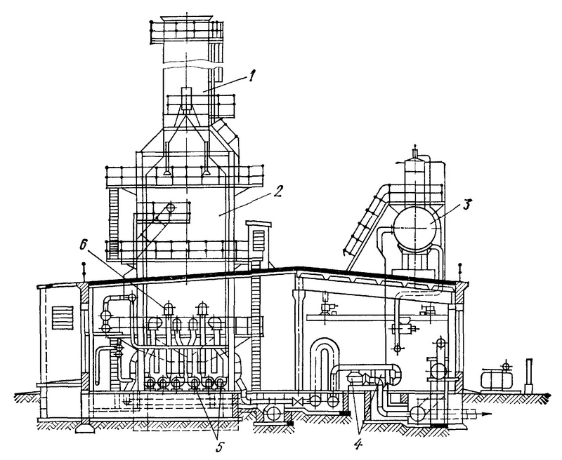
Picture 1.1 – Boiler plant scheme
Picrture 1.1 shows the scheme of the district heating
boiler plant with a
boiler (2). The boilers can run on liquid and gaseous fuels, so they
are equipped
with torches and nozzles (6). The air required for combustion is
supplied to the
furnace by blower fans (5), driven by electric motors.
Water is pumped into the boiler (4), driven by electric
motors. After passing
through the heating surface, the water is heated and goes to consumers,
where gives
some of the heat, and with reduced temperature returns to the boiler.
Flue gases
are removed from the boiler into the atmosphere through a pipe (1).
This boiler has a semi-open layout: the lower part of the
boilers (up to
a height of 6 m) located in the building, and the upper part of them
–
in the open
air. There are blower fans, pumps and control panel Inside the oiler
plant. On the
ceiling of the boiler plant installed deaerator (3) to remove oxygen
and carbon
dioxide from the water.
According to ongoing transformation processes distinguish
heating ,evaporating
and steam-overheating heating surface. Warmth from the combustion
products can be
transferred by radiation or by convection. According to this
distinction is made
between the heating surfaces:
Radiation heating surface receives warmth from gas is
mainly due to their
radiation. Much of this surface, which is located in the furnace,
called a shield.
Depending on the location shields are divided into side (pipes located
on the side
walls of furnaces), front (pipes are on the front wall), etc.
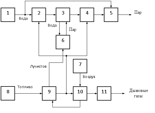
Picture 1.2 – boiler functional scheme
1 – Feed water pump, 2 – Economizer, 3 – cylinder, 4 – steam-overheater, 5 – steam-cooler 6 – evaporation elements, 7 – blow fan, 8 – spreader, 9 – furnace, 10 – air heater, 11 – smoke exhauster.
Despite on wide variations in the device for all boilers in fact proceed two identical main processes: combustion of fuel gas with the formation of high temperature (combustion) and the transfer of heat from these gases to water.
2. Goal and tasks of the research
Heat production is always a very important problem of
modern life, and the
modernization and improvement of this process is always relevant. At
the moment
most of the boilers in dire need of modernization, since they are
practically not
automated and a majority of processes managed by a person manually,
avoiding mistakes.
As a rule, on the majority of boiler plants, most of the
regulatory boiler
parameters still work in manual mode, what leads to serious
environmental pollution
and inefficient use of fuel in the modes of surplus or deficit air for
combustion.
The purpose of this paper is to analyze the technological
parameters of the
gas furnace unit for further automation. Need to increase the
efficiency of flue
gas control device by taking into account the composition of waste
gases and heat
load.
The paper identified the following objectives:
1) analysis of the individual subsystems of the gas
boiler as local objects
of automatic control;
2) synthesis system of automatic control of technological parameters of the flue gas devices;
3) analysis of the stability of automatic control systems to changes in thermal load and the parameters of combustion.
3. Analysis of existing systems of air supply mechanisms in boiler plant
Automated system of air supply mechanisms is designed for
performance management
of blowing fan and smoke exhauster of the boiler, using frequency
converters in
accordance with the technological regulations and modeline map and for
effective
combustion and saving fuel in thermal power and steam generation heat
supply and
provide consumers with hot water, save energy, improve equipment
reliability, informing
staff about the course of the process.
Automated System performs the following functions:
- collection, processing of analog and digital signals;
- control of process parameters: a rarefaction in the
furnace and the combustion
air pressure depending on the gas pressure (in accordance with modeline
map – the
ratio of the gas-air);
- automatic and remote control of executive mechanisms;
- control of technological processes in real time;
- testing and self monitoring equipment;
- protection against the destruction of software and
unauthorized access
to information;
- protection of electric motors driven by emergency modes
of operation (overload,
phase loss, low and high voltage coupling breakage, etc.);
- automatic reclosing draft machines in the mode of
ventilation of the boiler
with the disappearance and subsequent reduction of system voltage power
supply;
- formation of a warning signal in error situations
The purpose of creation and implementation of an
automated system is to achieve
optimal production and economic, technological and technical parameters
of the boilers
through the introduction of modern technologies and advanced management.
Reaching the main goal is provided by:
- improving the accuracy of controlling the parameters of
the process;
- high efficiency of process control;
- the expansion of information and control system
functions;
- provision of sufficient, reliable and timely
information about the process
and status of equipment for operational management by personnel;
- increasing the productivity of maintenance staff;
- decrease the influence of human factors on the
production process;
- savings in electricity consumption (on average 35%);
- a small saving of gas consumed.
The objects of control and automated management system
are:
- air supply system for combustion;
- the regulatory system of rarefaction in furnace.
Conclusion
Heat production is always a very important problem of
modern life, and the
modernization and improvement of this process is always relevant. At
the moment
most of the boilers in dire need of modernization, since they are
practically not
automated and a majority of processes managed by a person manually,
avoiding mistakes.
One of the main problems in the boiler plants, in
economic and environmental
issues, is the fact that do not regulated power of smoke exhausters and
blow fans.
The engines all the time working at maximum capacity, and the operator
controls
the boiler air supplying and waste gas exhausting manually opens or
closes the gate.
Due to a management system engines, wear faster, harmful emissions goes
into the
atmosphere because of lack of air or loss of efficiency due to the
excess air. The
ideal ratio for the combustion air / gas – 1/10, but actually use
1/8-1/7, and because
of manual configuration can be brought down to the 1/3, what leads to
high fuel
losses and to increase the content of harmful gas emissions .
Creating an automatic control system fuel and air supply
into boiler furnace
substantially will reduce costs and harmful emissions into atmosphere.
By
measuring the amount of oxygen in waste gases and taking into account
thermal
load at a particular time, you can effectively control fuel and air
supply to
maximize efficiency.
References
- Цыбрий И.К. Основы автоматического управления (учебное пособие) / И.К. Цыбрий. – Ростов-на-Дону, 2008. – 178 с.
- Эстеркин Р.И. Промышленные парогенерирующие установки / Р.И. Эстеркин. – Л.: Энергия, 1980. – 400 с.
- Гусев
Ю. М. Основы проектирования котельных
установок / Ю. М. Гусев. – [изд. 2-е, перераб. и доп.] –
М.: Стройиздат, 1973.
– 248 с.
- Роддатис К.Ф. Справочник по котельным установкам малой производительности / К. Ф. Роддатис, А. Н. Полтарацкий. – М.: Энергатомиздат, 1989. – 488 с.
- Равич М. Б. Эффективность использования топлива / М. Б. Равич. – М.: Наука, 1977. – 345 с.
- Справочник
эксплуатационника газовых котельных / [под ред.
Е. Б. Столпнера]. –
Л.: Недра, 1976. – 608 с.
- Чепель В. М. Сжигание газов в топках котлов и печей и обслуживание газового хозяйства предприятий / В. М. Чепель, И. А. Щурю – Л.: Гостоптехиздат, 1980. – 376 с.
- Павлов И. И. Котельные установки и тепловые сети / И. И. Павлов, М. Н. Федоров. – [2-е изд., перераб. и доп.] – М.: Стройиздат, 1977. – 301 с.
- Газоанализаторы-газосигнализаторы отходящих газов [Электронный ресурс] / НПП «ОРИОН», 2010. – Режим доступа: http://www.orion.com.ua/production20.htm
- Деев
Л. В. Котельные установки и их обслуживание / Л. В. Деев,
Н. А. Балахничев. – М.: Высшая школа, 1990. – 239
с.
- Авторизованный
сервис преобразователей частоты [Электронный ресурс] / ООО «НПП
РИЦ», 2010. –
Режим доступа: http://www.nppric.ru/index.php/preobrazovateli-chastoty-abb
- Липов Ю. М. Котельные установки и парогенераторы / Ю. М. Липов, Ю. М. Третьяков. – Москва-Ижевск: НИЦ «Регулярная и хаотическая динамика», 2003. – 592 с.
- Бузников Е.Ф. Производственные и отопительные котельные / Е.Ф. Бузников, К.Ф. Роддатис, Э.Я.Берзиньш. – [2-е изд., перераб.] – М.: Энергатомиздат, 1984. – 248 с.
- Сосков В. И. Технология монтажа и заготовительные работы: учеб. [для студ. выс. учеб. зав.] / В. И. Сосков. – М.: Высшая школа, 1989. – 344 с.
- Янкелевич В. И. Наладка газомазутных промышленных котельных / В. И. Янкелевич. – М.: Энергоиздат, 1988. – 216 с.
- Частухин В. И.
Тепловой расчет промышленных парогенераторов /
В. И. Частухин. – К.:
1982. – 182 с.