")
Abstract
Content
- Introduction
- Relevance of the topic
- The goals and objectives of the research
- Increasing the operational reliability of pipeline systems transporting gas environments
- Protection of pipelines against corrosion
- The main methods of corrosion protection of pipelines
- Findings
- References
Introduction
Pipeline transport – one of the most effective and efficient means of transporting gaseous substances. This is – an environmentally friendly mode of transport, has a low cost, continuous pumping process, the possibility of widespread laying, etc. The use of pipelines is more effective than the use of road and rail transport, to reduce the risk when transporting gas environments.
Operation of pipelines occurs under stringent conditions, as they are exposed to various stresses – the internal pressure, axial tensile or compressive stress, the pressure of the soil backfill and movable assets, temperature extremes.
All these factors contribute to the development of corrosion of the inner and outer surfaces of the pipe wall, and as a consequence – leakages and accidents. It is for this reason that more attention is paid to the reliability and efficiency of the pipelines.
Prediction of the operating conditions at the stage of the pipeline design allows to increase the reliability of the pipeline, to prevent possible accidents during operation.
Relevance of the topic
Every year, the environmental health of our environment is getting worse and worse... A growing number of factors affecting the environmental
field – a growing number of industrial enterprises, and with them increases and the amount of harmful emissions. That is why the stricter
requirements for the quality of the equipment to its reliability (to ensure adequate environmental safety).
Do not sidestep these requirements and gas industry. Reducing the negative impact and influence of pipelines on the environment in the process of their construction and operation is one of the priorities of modern construction.
Therefore, the development of technical solutions to improve the reliability of pipelines and reduce the human impact on the environment is a pressing problem today.
The goals and objectives of the research
The main goal is to develop methods to improve the operational reliability of pipeline systems transporting gas environments.
Objectives:
– To analyze the developments in this direction;
– Highlight the main characteristics of the studied pipeline, to analyze data on the state of the test pipe;
– Design a model of a gas pipeline to strength calculations, to develop ways to improve operational reliability and environmental safety [2].
Increasing the operational reliability of pipeline systems transporting gas environments
Trunk pipelines are an integral part of the global transportation system gaseous products. Consider a more detailed discussion of these systems [1 – 2].
With the gas flows through the field gas gathering point for capture by the collector of the gas treatment plant, which produces gas drying, removal of mechanical impurities, carbon dioxide and hydrogen sulfide. The gas supplied to the main compressor station, and then – in the main gas pipeline (Figure 1).
For the effective operation of the pipeline necessary to maintain the gas pressure along the entire length of the route – set for this compressor station (CS) with an interval of 80 – 120 km.
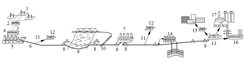
Figure 1 – Typical layout of the main gas pipeline equipment
1 – crafts, 2 – gas gathering point, 3 – fishing collector;
4 – Installation of gas treatment; 5 – main compressor station (CS);
6 – main line 7 – Interim CS; 8 – linear closures;
9 – underwater passage from the backup thread; 10 – go under the railway;
11 – removal of the gas pipeline; 12 – gas distribution station (GDS); 13 – the final GDS;
14 – station underground gas storage (UGS); 15 – gas control point (GCP);
16 – Power Station, 17 – Gas Processing Plant (GPP)
Objects CS project in block–complete version. In most cases, the CS are equipped with centrifugal blowers driven by gas turbines or electric motors. Currently equipped with a gas turbine driven more than 80% of the CS, and the electric drive – about 20%.
By line facilities include proper header pipe, line closures, gas purification units, transitions through artificial and natural barriers, corrosion protection stations, drainage devices, and include a line of technological communication, branches off from the main pipeline to supply a portion of the transported gas to consumers and linear structures operational services (LES) [3 – 4].
The distance between the line shut – off devices (valves) should be no more than 30 km. Control of linear valves should be provided remotely from the premises of the operator compressor station, as well as manual in place. Linear valves should be fitted with automatic failsafe mechanisms.
With parallel laying two or more gas pipelines in a technological corridor provides connection with their jumpers valves. Jumpers must be placed at a distance of not less than 40 km and less than 60 km from each other in line valves, as well as before and after the compressor stations.
Distribution stations (GDS) are designed to reduce (reduction) of the gas pressure to the operating pressure of the gas distribution customers. GDS is also equipped units of accounting and purification plants and odorization (giving it a peculiar smell to facilitate the detection of gas leakage to prevent hazardous situations and poisoning of people).
After GDS gas enters the gas network of settlements, which supply gas to the place of consumption. The reduction and to the extent necessary to maintain the gas pressure in the gas distribution network is carried out on the gas control points (GCP). For large gas consumers also include thermal power plants and gas processing plants (GPP).
For smoothing uneven consumption of gas major cities and towns are built station underground gas storage (UGS). To pump gas into underground storage facility is equipped with its own UGS compressor station.
The auxiliary line facilities include the main gas pipeline link pipeline service road, helicopter pads, pad emergency stock of pipes etc.
Depending on the specific operating conditions of the main structures of the composition of the gas pipeline is subject to change. Thus, in the short–haul pipelines may not be interim COP. If the produced gas is not hydrogen sulfide or carbon dioxide, the need for plants for gas purification from them is eliminated. Stations are built underground gas storage is not always the case.
Based on the magnitude of the working pressure gas pipelines are divided into two classes [5]:
1st class – at an operating pressure in excess of 2.5 MPa to 10 MPa, inclusive;
2nd class – at an operating pressure of more than 1.2 MPa to 2.5 MPa inclusive.
The length of the gas pipeline is typically from a few tens to several thousands of kilometers, and the diameter – from 150 to 1420 mm, inclusive. Most of the gas pipeline has a diameter of 720 mm to 1420 inclusive.
In the operation of pipelines are subjected to different loads – internal pressure, the pressure of the soil backfill and movable assets, temperature extremes, the axial tensile or compressive stresses. These factors contribute to the development of corrosion on pipe walls – which, as known, is a major cause of accidents.
Protection of pipelines against corrosion
The pipeline, laid in the ground, exposed to soil corrosion and extends above the ground – atmospheric. Corrosion of metals called destruction or alteration of the properties caused by chemical or electrochemical processes in interaction with the environment. The nature of interaction of the metal with the environment are two main types of corrosion: chemical and electrochemical [6 – 7]..
Chemical corrosion refers to the cases of changes in the properties of the metal by chemical reactions without the occurrence and flow of electric current. This type of corrosion include gas corrosion and corrosion in non–electrolytes.
Gas corrosion occurs as a result of interaction of a metal with a highly preheated gas in the absence of moisture (e.g., corrosion of gas turbine blades, scale formation by thermal treatment of metal, etc.).
Corrosion non–electrolytes – destruction metal in liquid or gaseous media nonconducting (corrosion by reacting with oil containing sulfur).
Galvanic corrosion – is the oxidation of metals in conductive media, accompanied by the formation and the flow of electrical current. Thus different regions on the metal surface having anode and cathode portions. Corrosion damage are formed only on the anodic sites.
By electrochemical corrosion processes include:
– electrolytic corrosion (liquids, conducting electric current: river and sea water, salt solutions, acids and bases);
– soil corrosion – the destruction of the metal under the influence of the soil electrolyte;
– galvanic corrosion – corrosion of metal structures under the influence of stray currents;
– contact corrosion – corrosion of metals in the presence of water caused by the direct contact of two or more metals with different electrochemical potential;
– atmospheric corrosion – the destruction of the metal in the medium of air or any other wet gas;
– biocorrosion – corrosion, vital activity of microorganisms that produce substances that accelerate the corrosion process.
Process corrosion begins from the surface and extends inward (Fig. 2). Distinguish solid local corrosion.
When all the solid corrosion metal surface coated with corrosion products. Non–uniformity of uniform corrosion is directly proportional to the aggressiveness of the corrosive environment.
Local corrosion – the destruction of the metal surface in some areas. The following types of localized corrosion:
– spots (the thickness of the layer of corrosion products much less than the area of the spot);
– ulcer (depth of damage is significant and commensurate with its area);
– Point (pitting) – depth of damage is much greater than its diameter. Pitting into a through under favorable conditions,
the corrosion processes.
– subsurface – swelling in the form of blistering and delamination of the metal;
– intergranular (extends along the boundaries of metal crystals and leads to loss of strength and ductility);
– structure–selective (broken any one alloying element);
– corrosion cracking (derived from a combination of corrosion and mechanical stress on the metal).
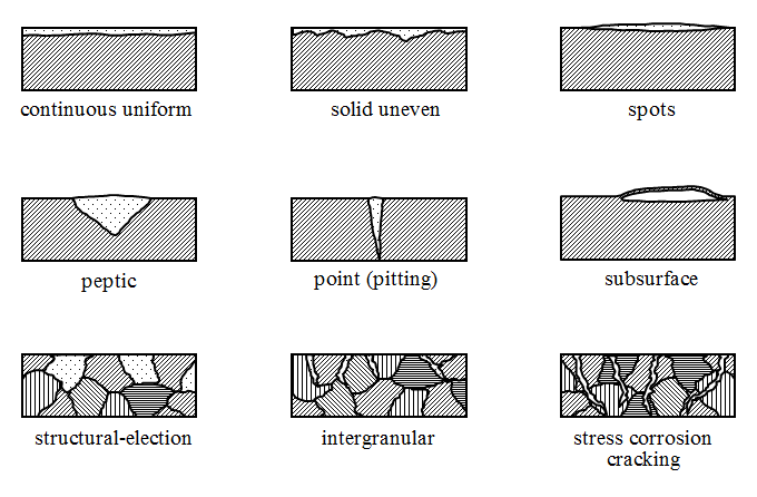
Figure 2 – The main types of corrosion damage
Local corrosion is the cause of kontsetrat stress, so it is more dangerous than solid.
The intensity of corrosion is affected by various factors (Fig. 3 and 4):
– heterogeneous composition of steel (contained in steel alloying elements and impurities favor the formation of corrosive
vapor in a hostile environment);
– heterogeneity conditions at the metal surface (scratches, dents, weld slag on the metal surface results in the formation
of anode and cathode sections and a corrosion centers);
– heterogeneity of environmental conditions: different soil moisture in the pipeline and various aeration
(oxygen access to the pipeline sections);
– transported medium heterogeneity (the presence of water and dissolved salts can result in the formation of corrosion
ribbed inner surface of the conduit).
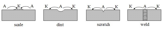
Figure 3 – Effect of the microstructure of the metal surface on the intensity of the corrosion process
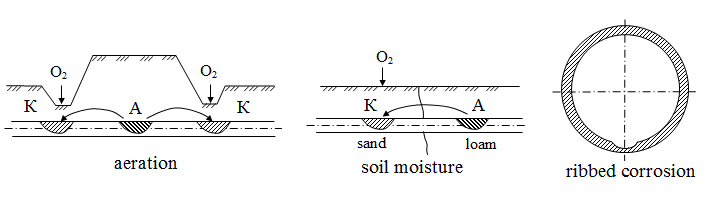
Figure 4 – Effect of inhomogeneity of the intensity of the corrosion process
The main methods of corrosion protection of pipelines
The methods involve extending the life of the pipeline, conventionally divided into four groups.
– Passive protection. Is applied to the surface of the pipe insulating protective coatings based on bitumen, polymer
ribbons or sprayed polymer. Insulating coating must possess confluence of high dielectric power, adhesion, mechanical strength,
water resistance, elasticity, biological stability, heat resistance, durability and nedifitsitnostyu.
– Introduction metal components increases the corrosion resistance. The method is applied at the manufacturing
stage of the metal. Simultaneously, the metal impurities are removed, reducing corrosion resistance.
– The impact on the environment. The method is based on the introduction of corrosion inhibitors to deactivate
the aggressive environment.
– Active protection. By this method include the cathode, the tread and drainage protection.
The most widely used method of passive protection – covering the inner and outer walls of the pipe insulation materials. In recent years, to improve mechanical properties and durability of coatings of insulating materials and apply them nanostructural reinforcement fillers [8].
Figure 5 – Layers of insulation
(animation: 5 shots, 5 cycles of recurrence, 72 kilobytes)
1 – pipe; 2 – chromate layer; 3 – adhesive layer;
4 – polyethylene layer estrudirovannogo nanostructured fillers; 5 – inner layer of insulation
By using nanotechnology materials will rise to a new level of quality pipes with corrosion–resistant coating. This will increase their competitiveness, increase the service life and change the physico–chemical properties of the coatings. This fact is important in connection with the construction of gas pipelines in difficult climatic conditions, areas with large and sudden changes in temperature.
The use of carbon nanotubes and carbon nanofibers as fillers, polymers can improve a number of indicators:
– To increase the electrical conductivity;
– To increase the thermal conductivity, heat resistance, the ignition temperature;
– To give the anti–static properties;
– To improve the mechanical properties (tensile strength and tear, modulus and to increase the ultimate tensile; increase durability);
– To increase the adhesion and extend the temperature range of use ( – 60 to 250°C);
– To provide resistance to aggressive media.
Findings
Thus, we can conclude that the determining criterion of ecological safety of pipeline systems is their structural reliability – one of
the main indicators of quality of any design (system), is its ability to perform specified functions, retaining its performance
characteristics for the required period of time life cycle
.
Refusal gas pipeline, which is manifested in the local loss of integrity of the pipe wall, pipe fittings, or a total loss of strength as a result of destruction, usually leads to substantial environmental damage with possible irreparable consequences for the environment.
One way to prevent the destruction of the pipe wall is to use a new high–quality materials for insulation coating.
Adding the manufacture of insulating coatings carbon nanofibers – effective way to improve the physical and mechanical characteristics of the insulating material based on polyethylene – strength and durability of the polymer material based on polyethylene increases several times the coefficient of friction decreases.
This master's work is not completed yet. Final completion: December 2013. The full text of the work and materials on the topic can be obtained from the author or his head after this date.
References
- Нечваль Андрей Михайлович. Проектирование и эксплуатация газонефтепроводов: Учеб. пособие / Уфимский гос. нефтяной технический ун–т. – Уфа: ООО ДизайнПолиграфСервис, 2001. – 166 с.
- Селезнев В.Е., Прялов С.Н. Методы построения моделей течений в магистральных трубопроводах и каналах / М.: Едиториал УРСС, 2012. – 560 с.
- Техника и технология транспорта и хранения нефти и газа / Ф.Ф. Абузова, Р.А. Алиев, В.Ф. Новоселов и др. – М.: Недра, 1992. – 320 с.
- Трубопроводный транспорт нефти и газа / Р.А. Алиев, В.Д. Белоусов, А.Г. Немудров и др. – М.: Недра, 1988. – 368 с.
- СНиП 2.05.06–85*. Магистральные трубопроводы / Госстрой России.: ГП ЦПП, 1997. – 52 с.
- Ясин Э.М., Черникин В.И. Устойчивость подземных трубопроводов / М.: Недра, 1967 г., 120 с.
- Противокоррозионная защита трубопроводов и резервуаров / М. В. Кузнецов, В. Ф. Новоселов, П. И. Тугунов и др. – М.: Недра, 1992. – 238 с.
- Научно–технический журнал "Наноиндустрия", от 07 мая 2009 г.