Abstract
Content
- 1. The relevance of the topic
- 2. Тhe goal and tasks of research
- 3. The current state of the problem of the study
- 3.1 Analysis of the structural elements gear couplings, contribute to levelling the load in the connection
- 3.2 Analysis of operating conditions of toothed couplings
- Conclusions
- References
1. The relevance of the topic
Gear couplings are used in the equipment for connection of the shaft, interacting in the presence of errors of installation, and their loading and flexible ability to depend on a number of factors, including the type of the geometry of the side surface of the tooth of the bushings. So, the most promising directions of perfection of the design gear couplings is the production of tooth bushing with spatial modification, which imparts to transfer the ability to compensation mounting of the shaft while keeping the line of contact between the teeth and even distribution of the load. However, all known spatial tooth geometry are used to compensate for any one value of the error mounting of the shaft, or to compensate for one type of errors. The operation of gear couplings in conditions other than those for which they were designed, in some cases, leads to the localization of contact between the one or two diametrically opposite pairs of teeth in the dot-кромочном the nature of the contact.
Technological methods of cutting teeth with spatial geometry, providing the connection of linear contact and uniform distribution of the load between the teeth, are based on observance of two conditions of the second way of Olivier. Observance of these conditions leads to complication of kinematics of the relative motions of the tool and workpiece, and to the full extent they can be implemented on the operation of the finishing of the sleeve with the use of special technological equipment and the cutting tool. However, in some cases it is possible to use tooth geometry, close to a set of spatial received on the serially produced зубообрабатывающем equipment. Therefore, questions on the development of technological maintenance of reception of tooth geometry, close to a set of spatial, with the use of serially-manufactured of equipment are relevant.
2. Тhe goal and tasks of research
The aim of the research is the development of design and technological provision of uniform distribution of the load on the connection between the teeth hub and magazines and improving the load-carrying and compensating the ability of toothed couplings at the expense of change of a rigidity of the rim clips.
The main objectives of the study:
- Undertake an analysis of the existing structural elements gear couplings, contribute to levelling the load in the connection, the operating conditions of toothed couplings and technological methods of forming of spiders hub and magazines.
- Investigate the stress-strain state clips gear coupling in case of errors mounting of the shaft.
- To develop a design ensuring uniform distribution of the load on the connection between the teeth hub and magazines and increase of the carrier and compensatory abilities gear couplings.
- To develop technological maintenance of manufacture magazines gear coupling with low rigidity rim magazines.
- To develop the technological equipment for the manufacture of clips gear couplings with low rigidity rim clips.
3. The current state of the problem of the study
3.1 Analysis of the structural elements gear couplings, contribute to levelling the load in the connection
Gear couplings are widely used for connection of the shaft units of various machines, due to such of their dignity as high load capacity, with a relatively small overall dimensions, reliable operation at high speeds, the ability to compensation arising during installation shafts and application for cutting spiders standard cutting tools [1-8].
At the present time there are a large variety of designs gear couplings. The basis of the design of the gear couplings supposed connection bracket with internal teeth with the rectilinear forms and Bush with the outer teeth of the gear ratio is equal to 1. So DSTU 4227 (GOST 5006) provides for the following types of couplings[1-10]:
- Type MH – coupling for direct connection of the shaft (Fig. 1).
- Type of MMW – coupling for connection of the shaft with the use of the intermediate shaft (Fig. 2).
Coupling type MH (Fig. 1A) consist of two gear sleeve and two gears clips. The state standard of Ukraine it is allowed to manufacture gear drives of different versions: gear sleeve with a cylindrical bore (Fig. 1A), gear sleeve with a cylindrical bore and face mounting on the shaft(Fig. 1B); gear sleeve with tapered bore (Fig. 1C). Coupling type MH can be performed by using the split (Fig. 1A) and clip (Fig. 2).
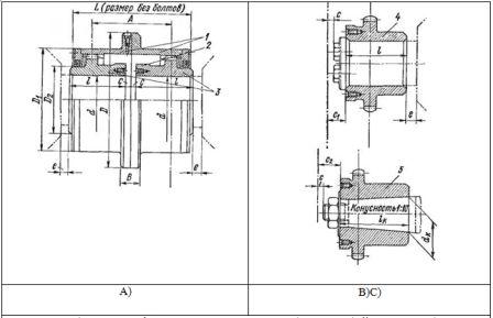
Fig. 1 – Gear couplings type MH: 1 – toothed shell; 2 – Burt to check the alignment of the shafts; 3 – gear sleeve with a cylindrical bore; 4 – gear sleeve with a cylindrical bore and face mounting on the shaft; 5 – gear sleeve with tapered bore
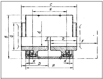
Fig. 2 – Design of the coupling type of MH with clip
Coupling type MMW (Fig. 3) are a set of two boxes, each of which consists of a gear hub, magazines and the flange of the coupling half.

Fig. 3 – Gear couplings type MMW
(Animation: contains 10 frames, 5 cycles repeat, amount of 155 KB)
(1 – toothed shell; 2 – cover; 3 – gear sleeve)
The teeth of the bushings and clips perform track belt with involute profile (Fig. 4) and angle coupling α=20 degree according to GOST 13755-81 two standards of accuracy: normal in the peripheral speed at the initial circle gear pair v < 15 m/s and higher accuracy at v > 15 m/s.
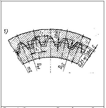
Fig. 4 – Involute tooth profile hub and clips
For reduction of losses on friction and increasing durability of tooth gear connection grease. Type of lubricant is selected depending on the temperature conditions of operation [1-4].
Balancing and load capacity of toothed couplings and nature of contact between teeth depends on the design of elements of toothed couplings: the values of the side of the gap in a synchronous connection, the distance between the centers spiders bushings, width of the sleeve bushing, the geometry of the side surface of the tooth hub, rim design hub and magazines, etc [11-14]. ]. Let's consider the design features of the details of toothed couplings, affecting their passivity.
Increased rigidity of elements gear couplings leads to a concentration of the load by axes misalignment of the shaft, which affects the contact strength of the teeth, and on the nature of the load distribution between the teeth in the limits of the zone contact, and, consequently, the loading of the pillars connected by the shaft and the increase of the intensity of wear of the teeth.
The ferrule is the most hard element gear coupling. So one of the ways to increase bearing and compensating ability of toothed couplings is to increase the flexibility of the rim magazines.
Increase of flexibility of the rim clips leads to an increase in the zone of contact between the teeth hub and magazines and a more equitable distribution of gaps and the load between them.
The most modern measures to increase the carrier and compensating ability of toothed couplings is the manufacture of teeth with different types of spatial geometries on the side of the tooth hub. The resulting geometry of the lateral surface of the tooth ensures the increase of the contact spot in the operation, leads to a simultaneous increase of the carrier and compensating ability of toothed couplings.
Getting the spatial geometry of a tooth bushings needed for the compensation of all of the errors of assembling and manufacturing of teeth, is difficult because of the lack of equipment able to recreate in full measure to the movement of the workpiece and the tool. In consequence of which were developed different variants of tooth geometry close to the spatial [16-19].
In the papers [15-20] describes a gear coupling, consisting of clips with internal teeth with the rectilinear forms and hub of the teeth, on the side, which implemented the spatial geometry of the obtained kinematic method. When the contact line on the surface of the tooth clips are described by a system of equations:
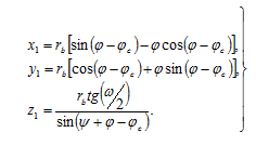
where φc – angle offset of the beginning of involutes; rb – radios of the main cirde; φ – angle unrolledness profile; ψ – angle of rotation of connection; ω – angle skew of teeth hub on tooth magazines.
Coordinates of contact points on the surface of the tooth bushings are defined by the system of equations:
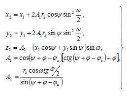
Designed and manufactured in accordance with the recommendations of the papers [20]a gear coupling can be used to connect a несоосных shafts of heavy machinery in the corners, the skew greater than 45'. This increases the load capacity of the coupling due to the increase in the coefficient of covering and increase of the contact spot of a tooth. However, when you change the operating conditions, at which the connection tooth hub and magazines were calculated, i.e. when you change the real-angle skew the connection to the occurrence of the dot-edge contact of two diametrically located pairs of teeth, which will reduce the load capacity of the teeth.
Thus, the main disadvantage of the considered geometry of surfaces of teeth of the bushings gear couplings is not their universality. They either compensate for one of the types of errors mounting coupling halves, or were originally designed for the compensation of any of the final value of one of the types of error of installation (for example, angle skew), while even a slight deviation from this value may cause a sharp deterioration of the operational capacity of toothed couplings.
Together with the gear couplings and their separate elements have high rigidity and are able to transfer large torques at work in ideal circumstances, when there are no or minimized errors mounting of the shaft. However, the provision of high precision mounting shaft is not always rational and achievable in conditions of concrete production. So, gear couplings and their elements work in conditions of existence, sometimes significant errors mounting of the shaft, which leads to the edge of the contact of the teeth and uneven distribution of gaps and the load on the connection. What contributes to the high rigidity of construction, as the gear couplings and its individual elements. Thus, the choice of a rational rigidity of gear couplings and of the elements should lead to increase of their load capacity, reduce the adverse impact of the errors of installation shafts and as a consequence increase the durability of toothed couplings.
As a result of all above stated can be concluded, that in order to improve the operational performance of toothed couplings must be on the basis of their existing designed and conducted research to develop new more universal design gear couplings. The universality of the structures, which consists in the creation of the lateral surface of the tooth hub spatial geometry able to compensate for all types of errors mounting coupling halves of a change in their values in the set limits and ensuring of the required flexibility of their elements.
3.2 Analysis of operating conditions of toothed couplings
A number of scientists were carried out long-term studies of the operating conditions of toothed couplings to determine the factors that affect their performance.
In work [21] ] the influence of the deformability of gear on the nature of their work, also in the General picture of the loaded teeth of the influence of the errors of manufacturing, the manifestation of which is inseparably connected with the manifestation of the deformation of teeth. Peculiarities of work, design and kinematics gear couplings are described in work [22]. In this paper noted that the increased temperature of the oil to the gear coupling is not due to a high coefficient of friction gearing, and заклиниванием tooth, which is caused by improper design of the coupling. Also from the kinematic considerations it is established, that must be complied with equal diameters processing of outer edges of the teeth and working surfaces. It is proved that in the design of gear couplings, according to the proposed rules, provided for by the Standard of angular and radial offsets could be increased in order for the preservation of the rigid requirements to the thickness of the outer diameter of the tabs.
In work [23] for a more complete solution of the problem of the formation of the gaps between the teeth couplings, because the errors of manufacturing and installation of hubs significantly affect the distribution of gaps between the teeth couplings, what is the cause of their non-uniform loading.
In the most severe cases of imposing large variable loads on large imbalances, there arises a problem of longitudinal modification to ensure the efficiency of the gear [24]. ]. The key to solving this problem is to use the theory of natural barrel given the range of loads, as well as elastic pliability of the body of the tooth.
In work [25] presents the algorithm, which can be used for geometry-kinematic analysis of any gear. The algorithm consists of universal and replacement parts. Due to the change of shift part of the algorithm can be rebuilt on the analysis of different gear.
As a result of friction and wear changes the geometry of the teeth that leads to change of conditions of their work. For accounting changes tooth geometry in the paper [26] attempt to predict the form of the profiles of tooth gearings as a result of their wear and tear on the basis of the theory of entanglement tooth [27], i.e., the teeth have as a result of wear arbitrary (although close to involutes) profile.
The geometrical characteristics of the gears are defined on the basis of the conditions of the contact and bending their strength. The influence of errors mounting spiders to contact voltage set forth in[28-29], the methodology of calculation of contact stress on the teeth are given in works [30-32], the assessment of the impact of the length of overhead lines is described in [57].
Fundamental research of friction and wear of materials are the theoretical basis for the assessment of the contact endurance of tooth gearings of various criteria of failure. Using their results when estimating resistance of the contact surfaces of teeth of contact damage possible on the basis of a correct account of the conditions of loading and deformation of teeth in different phases of the engagement. In connection with this, analyzed: the criteria for the rejection of the contacting surfaces of the teeth in the contact loading; the critical points of the active part of the surface of the teeth on one or more criteria of refusal; methods of assessment of the main estimated parameters determining the resistance of the contact surfaces of the teeth pin destruction; the impact of structural and technological factors of the resistance of the contact surfaces of the teeth pin destruction [34].
The most effective method of reducing the concentration of contact stresses as a result of the initial application of the tooth is their longitudinal modification. It is known that the longitudinal modification of the teeth leads to increase of the level of contact stresses in comparison with the nominal touching cylinders, imitating the surface of the tooth. On the other hand, the increase in longitudinal curvature of the teeth, localizing contact, making transmission less sensitive to errors of installation [35].
In the paper [36] a technique for determination of individual gear in the individual situation on the condition of contact fatigue. Methods are based on the results of the analysis of work of a gear coupling with the use of the mathematical apparatus of the theory of opportunities. The problem of estimation of reliability of gear at the stage of operation occurs after the transfer of the normal or guaranteed term of its exploitation, as well as after emergency situations.
Numerous tests and operational experience of toothed couplings show that the main types of their failure is the tooth wear sleeves and magazines, leading, ultimately, to the fatigue damage of teeth hub in view of the unwarranted their tapering. Thus, to increase the service life of the coupling must be to increase the thickness of the tooth hub, correspondingly reducing the thickness of the tooth magazines, taking into account the differences in the intensity of their wear [37].
In the paper [38] the results of the current study load in the teeth and power factors, arising in the coupling with the misalignment of axes, brought down to a simple calculation dependencies.
The definition of the distribution of stresses on the length of the barrel-shaped teeth were set out in [39]. Conclusions are made that the tooth with the values of barrel, close to the researched, there has been a significant increase in the voltage in галтели tooth in the middle of its length. Reduction of bending fatigue strength of a barrel-shaped teeth with large quantities of barrel is a consequence of excessive irregularity of the distribution of stresses on the length of the tooth.
On the basis of assumptions about the small area of contact in comparison with the size of the contacting bodies, the Hertz theory are considered only contact deformation and, as a consequence, the convergence of the contacting bodies. Load in contact barrel of a tooth with other tooth favorably differs from the concentrated force, but being distributed in a small area, causes a bending of the tooth that are comparable to the convergence of the tooth, which significantly reduces the contact voltage compared to the determined by Hertz.
As a result of these studies it has been hypothesized that the optimal for the work of the gear coupling, is the implementation of the spatial coupling between the teeth hub and magazines. That is obtaining the tooth geometry, which corresponds to their natural wear in the process of work.
Thus, to increase the load capacity [40] gear couplings is necessary to ensure contact between the largest possible number of pairs of teeth hub and magazines. To achieve this result can be due to the implementation of the spatial coupling tooth hub and magazines and choice of rational rigidity of elements of a gear coupling [41].
Conclusions
1. To date, the existing connection tooth hub and magazines, built on the basis of any of the geometry of the side surface of the teeth, are not universal and are not able to fully offset arising in the process of manufacture, installation and operation of errors connected shafts, including due to the high rigidity of the rims hub and the gear couplings.
2. Implementation of the spatial coupling tooth hub and magazines and choice of rational rigidity rims hub and the gear coupling should contribute to improving the load capacity and durability gear couplings, at the expense of reduction of the level of bending and contact stress by providing a point of contact between the largest possible number of pairs of teeth hub and magazines.
3. Known technological methods for formation of teeth bushings gear couplings are mainly based on the traditional methods of producing cylindrical spiders and does not take into account the peculiarities of the conditions of interoperability tooth sleeves and collar in a gear coupling in case of errors mounting of the shaft .
This master's work is not completed yet. Final completion: December 2013. The full text of the work and materials on the topic can be obtained from the author or his head after this date.
References
- Айрапетов Э. Л. Зубчатые соединительные муфты / Э. Л. Айрапетов, Д. Б. Миржаджанов. – М.: Наука, 1991. – 250 с.
- Айрапетов Э. Л. Зубчатые муфты / Э. Л. Айрапетов, О.И. Косарев. – М.: Наука, 1982. – 128 с.
- Производство зубчатых колес: Справочник / С.Н. Калашников, А.С. Калашников, Г.И. Коган и др.; под общ. ред. Б.А. Тайца. – 3-е изд., перераб. и допол. – М.: Машиностроение, 1990. – 464 с.
- Тайц Б.А. Производство зубчатых колес / Б.А. Тайц – М.: «Машиностроение», 1975. – 512 с.
- Мокид Зубчатые муфты. Исследование и оптимизация / Мокид // Труды Амер. об-ва инженеров механиков. Сер. В. Конструирование и технология машиностроения. – 1968. – №3. – С. 1 – 10.
- Мирзаджанов Д. Б. Конструктивные методы выравнивания зазоров и скоростей скольжения на боковых поверхностях зубьев муфт / Д. Б. Мирзаджанов // Вестник машиностроения. – 1986. – №8. – С. 14 – 17.
- Андожский В.Д. Модификация головок внешних зубьев эвольвентных зубчатых колес / В.Д. Андожский, Н.И. Рогачевский // Вестник машиностроения. – 1985. – № 7. – С. 15 – 17.
- Андожский В.Д. Геометрический расчет модификации головок зубьев / В.Д. Андожский // Вестник машиностроения. – 1976. – № 5. – С. 39 – 42.
- Андожский В.Д. Модификация головок зубьев рейкой с линией модификации по дуге окружности / В.Д. Андожский // Вестник машиностроения. – 1978. – № 8. – С. 26 – 29.
- Заблонский К.И. Синтез оптимальной продольной модификации зубчатых передач с твердыми (НВ>350) поверхностями зубьев при учете режима нагружения / К.И. Заблонский, Р.А. Мацей, Б.М. Щекин // Технологические методы обеспечения качества зубчатых передач: Тез. докл. Всесоюз. науч.-техн. конф. В г. Свердловск 8-10 апр. 1981 г. – Свердловск: Урал. политехн. ин-т; М., 1981. – Ч. 2. – С. 112 – 114.
- Громан М.Б. Бочкообразный зуб / М.Б. Громан, П.С. Зак // Вестник машиностроения. – 1976. – №4. – С. 23 – 25.
- Котляров Б.С. Основы структурного синтеза модификации зубьев цилиндрических колёс и схем многоинструментальных роторных машин для их формообразования: автореф. дис. на соискание научной степени канд. техн. наук: спец: 05.02.02 – «Машиноведение и детали машин», 05.02.18 – «Теория механизмов машин» / Б.С. Котляров – Харьков, 1989. – 16 с.
- Сухоруков Ю.Н. Модификация эвольвентных зубчатых колёс: Справочник / Сухоруков Ю.Н. – К.: Техника, 1992. – 197 с.
- Котляров Б.С. Формообразование бочкообразных зубьев при применении роторных схем / Б.С. Котляров // Совершенствование конструкций и технологии зубообработки передач зацеплением. – Ижевск, 1984. – С. 38.
- А.с. 685451 СССР, МКИ В 23 F 1/00 Способ обработки зубчатых колёс / Н.Э. Тернюк, В.Б. Варшавский, А.А. Хлус (СССР). – №2418078/25-08; заявл. 04.11.76; опубл. 15.09.79. Бюл. № 34.
- А.с. 1255318 СССР, МКИ В 23 F 9/08 Способ обработки бочкообразных зубчатых колёс / В.А. Данилов (СССР). – №3755442/25-08; заявл. 19.06.84.; опубл. 07.09.86, Бюл. № 33.
- Данилов В.А. Диагональное зубофрезерование колёс с бочкообразными зубьями / В.А. Данилов // Вестник машиностроения. – 1989. – №10. – С. 133 – 138.
- А.с. 1404213 СССР, МКИ B23 F 5/12 Способ диагонального зубофрезерования колес с бочкообразными зубьями / В.А.Данилов (СССР). – № 4073589/31-08; заявл. 04.06.86; опубл. 23.06.88, Бюл. №23.
- Уткин Б.С. Исследование нагрузочной способности зубчатых соединений шпинделей прокатных станов. Автореф. дис. … канд.техн.наук. Курган. 1983. 18 с.
- Дымшиц И. И. Коробки передачи. Машгаз, 1960.
- Елисеев Ю.С. Деформации и погрешности в зацеплении и их роль в работе зубчатой передачи / Ю.С. Елисеев, И.П. Нежурин // Вестник машиностроения. – 1999. – № 8. – С. 28 – 31.
- Гроховский Д.В. Особенности работы и конструирования зубчатых муфт агрегатов / Д.В. Гроховский // Вестник машиностроения. – 2005. – №2. – С. 8 – 12.
- Мирзаджанов Д.Б. Влияние погрешностей изготовления и монтажа полумуфт на зазоры между зубьями муфт / Д.Б. Мирзаджанов // Вестник машиностроения. – 1985. – №10. – С. 56 – 59.
- Зак П.С. Перекосы тяжелонагруженных зубчатых передач и продольная модификация зубьев / П.С. Зак, А.Е. Уздин // Вестник машиностроения. – 1988. – №2. – С. 12 – 14.
- Шевелева Г.И. Алгоритм геометро-кинематического анализа зацепления зубчатых колес / Г.И. Шевелева, А.Э. Волков, В.И. Медведев // Вестник машиностроения. – 2004. – № 8. – С.3 – 9.
- Онищенко В.П. Прогнозирование формы профилей зубьев зубчатых передач в результате их износа / В.П. Онищенко // Прогрессивные технологии и системы машиностроения: Международный сб. научных трудов. – Донецк, Донец. гос. техн. ун-т., 1998. – Вып. 5. – С. 155–163.
- Онищенко В.П. Моделирование контакта несопряженных профилей зубьев зубчатых колёс / В.П. Онищенко // XXXV Sympozion “Modelowanie w mechaice” Polit. Polska, Katedra Mechaniki Technicznej Z. Gliwice. – 1996. – № 2 – P. 175 – 182.
- Айрапетов Э.Л. Роль кромочного контакта в обеспечении контактной прочности зубчатых колес / Э.Л. Айрапетов, Э.Д. Браун, Н.В. Чичинадзе, И.А. Копф, В.В. Корнилов // МиТОМ. – 2002. – №9. – С. 36 – 38.
- Попов А.П. Контактная прочность эвольвентного зацепления с учетом перекоса зубчатых колес / А.П. Попов, А.С. Каиров // Прогресивні технології і системи машинобудування: Міжнародний зб. наукових праць. – Донецьк: Донец. нац. техн. ун-т., 2007. – Вип. 34. – С. 183 – 189.
- Айрапетов Э.Л. Расчёт контактной нагрузки в зубчатых зацеплениях / Э.Л. Айрапетов, С.Э. Айрапетов, Т.Н. Мельников // Вестник машиностроения. – 1982. – № 10. – С. 3 – 6.
- Айрапетов Э.Л. Определение контактной деформации зубьев цилиндрических зубчатых колес / Э.Л. Айрапетов // Вестник машиностроения. – 1967. – №1. – С.32–35.
- Михайлов А.Н. Методика расчета распределения нагрузки по пятну контакта зуба зубчатой муфты, при перекосе осей валов / А.Н. Михайлов, Р.М. Грубка, С.А. Рыбина, Е.А. Буленков // Прогрессивные технологии и системы машиностроения: Международный сб. научных трудов. – Донецк, Донец. гос. техн. ун-т., 2002. – Вып. 19. – С. 151–157.
- Ристивоевич М. Влияние длины контактных линий на контактные напряжения зубьев цилиндрических зубчатых передач / М. Ристивоевич; Т. Лазович, Р. Митрович, М. Ристивоевич, Р. Митрович, Т. Лазович // Техника машиностроения. – 2001. – № 2. – С. 34–38.
- Айрапетов Э.Л. О расчетной оценке контактных разрушений на зубьях зубчатых колес / Э.Л. Айрапетов // Вестник машиностроения. – 1999. – №8. – С. 3 – 20.
- Айрапетов Э.Л. Расчет контактных напряжений в передачах зацеплением с локализованным контактом зубьев / Э.Л. Айрапетов, С.Э. Айрапетов, Т.Н. Мельникова // Вестник машиностроения. – 1985. – №12. – С. 6 – 8.
- Уткин В.С. Определение надежности зуба прямозубой зубчатой передачи по условию контактной усталости / В.С. Уткин // Вестник машиностроения. – 2007. – №3. – С. 25 – 28.
- Айрапетов Э.Л Создание и внедрение зубчатых муфт с равнопрочными зубьями / Э.Л. Айрапетов, В.С. Плотников, А.И. Робер, Б.С. Уткин // Вестник машиностроения. – 1991. – №5. – С. 22 – 23.
- Мирзаджанов Д.Б. Расчет нагрузок и усилий в зубчатой муфте при перекосе осей / Д.Б. Мирзаджанов, Е.В. Хворостов // Вестник машиностроения. – 1988. – №6. – С. 11 – 13.
- Семенча П.В. Распределение напряжений по длине бочкообразных зубьев / П.В. Семенча, Ю.А. Зислин, Н.Б. Шубина // Вестник машиностроения. – 1970. – № 12. – С. 22 –23.
- Финиченко В.А., Водолажченко А.Г., Осадчий А.С. Напряженно-деформированное состояние зубьев зубчатых муфт.[Электронный ресурс] – Режим доступа http://www.nbuv.gov.ua/portal/natural/Ptsm/2008_36/261-263.pdf
- Айрапетов Э.Л., Уткин Б.С., Лагутин С.А., Робер А.И. Совершенствование зубчатых муфт и шпинделей конструкции ЭЗТМ.[Электронный ресурс] – Режим доступа http://new.gears.ru/pdf/air/air_s2.pdf
