
Abstract
Content
- Introduction
- 1. Urgency of increasing treatment natural gas
- 2. Goals and objectives of the master's work
- 3. Hydrodynamic modeling a separator processes
- 3.1 Development of a 3D model of cold separator
- 3.2 Computer Simulation
- 3.2.1 Choosing software package for solutions
- 3.2.2 Design procedure
- 3.2.3 Simplifying the model and export geometry
- 3.2.4 Create covers and checking geometry
- 3.2.5 Making porous body
- 3.2.6 Create a Project
- 3.2.7 Setting the boundary conditions and perform calculations
- Conclusion
- References
Introduction
Natural gas, oil and coal – the main source of hydrocarbons.
Natural gas is widely used as a cheap fuel with high calorific value.
This is one of the best fuels for domestic and industrial needs. Natural gas is a valuable raw material for the chemical industry.
Natural gas – a mixture of gases formed in the bowels of the Earth anaerobic decomposition of organic matter.
gas coming from wells, it is necessary to prepare for transportation to the end user. The need for a Gas caused by the presence therein of impurities other than target components, cause difficulties during transportation or use. Thus, pairs Water contained in the gas under certain conditions can form hydrates or condense, accumulate in different places, making it difficult to Promotion gas hydrogen sulfide gas causes severe corrosion.
also when gas mixtures in addition to a gaseous contains condensate which creates a number of problems transportation: the formation of liquid plugs, which later – Break lines, increased corrosion of equipment and pipeline.
Condensate – vysokomponentnoe substance from which the useful components. It is a commercial product.
gas coming from wells, it is necessary to prepare for transportation to the end user – Chemical Plant, boiler room, city gas network. The need for a Gas caused by the presence therein of impurities other than target components, cause difficulties during transportation or use [1].
1. Urgency of increasing treatment natural gas
In the last decade, the consumption of natural gas market has undergone significant changes. More and more consumers prefer to buy liquefied natural gas (LNG), and both suppliers consumers have their own standards, which should correspond to let go of the raw material. Furthermore, natural gas from different fields characterized by its composition, for its processing requires different technology. Transported by pipeline natural gas differs in its characteristics of LNG. All of these problems can be divided follows.
1. Problems technology. Processing of natural gas fields has the following objectives:
• removal of contaminants: CO2, H2S and mercaptans (weak by corrosive acids) that cause corrosion of equipment;
• separation of heavy ends which hinder the transmission of natural gas pipelines;
• separation of substances that negatively affect energy figures material.
Removal of acidic impurities occurs amine units, using a direct chemical absorption (alkalization) of natural gas. Processing of raw materials with a high content of mercaptan requires special technologies.
Branch heavy hydrocarbons not only prevents the formation of liquid phase in gas, but also highlights important for industry gas – propane and butane, which are widely used for vehicles, in the home and for commercial enterprises. on the market receives liquefied petroleum gas (LPG).
These issues are relevant for both the provider and for consumers and their decision does not cause differences between participants market. At the same time the requirements on the calorific different countries are different, which requires not only coordination at compacts, but also the possible changes in the process raw material preparation to implementation.
2. A method of transporting natural gas causes not only different technological preparation of natural gas, but the decision problems with transport (construction, lease or purchase of LNG, production of insulated tanks, etc.). However, the decision of the questions promises lucrative contracts and expanding the number of market participants production / sales of liquefied natural gas in the world.
3.Typically, the main pipeline, which pumps natural gas, have a length of a thousand miles. transfer of gas through several sovereign states, which means possible economic and political problems. contractual relationship not always correspond to the realities of the market, due to long lead times contracts for the supply of products.
Today's interest in the use of computer analysis based on two factors of comparable importance. First – this is the actual need for tools to create competitive products where the use of the traditional "manual" calculations (even if implemented by computers) are not guarantee any significant improvement. And use traditional approaches becomes very difficult because of the human factor: the skills to pass the turned–based long–term adaptation of the application of mathematical models uzkoprofilnyh to the experimental results, no better than to master the universal numerical analysis tools. This selection at the end "consumer" of the engineering staff, in principle, is not: system of higher engineering education has also acquired a distinct emphasis on the development of "simulation" rather than systematic study of specific mathematical methods in together with the actual experiment.
A second, no less important reason for the popularity of programs, analysis, availability of offers at a relatively affordable and highly affordable software interface in combination with acceptable price computers. In organizations, in fact, is not no alternative – the "old" hard to reproduce, and the "new" is, like, became generally accepted, in the absence of the arsenal of the company or that the settlement package is not considered a sign of good taste. Provocative, in a sense, the role played by artists – sometimes they are set up to attract more and more complex "universal" without adequate tools is not that understanding, and even the idea of how this complex mathematics, algorithms, data functions. As practice shows, the vast majority of issues arising from the user, is not related to the actual methodology, and of particular concern different kinds of interface problems, the desire to be "on the cutting edge" in terms of supporting / absence of such a variety of operating systems, specialized hardware, exotic hardware funds, other things that distract from the final result. First of all, these results should be adequate models of real objects and processes.
2. Goals and objectives of the master's work
The main goals to improve the separation efficiency of natural gas are:
1. The development of measures to improve the efficiency of equipment separating the natural gas liquids;
Technical efficiency is characterized by the ability to maximize the impact of its construction in certain parameters (dimensions, capacity, weight, cost, etc.).
Indicators (criteria) the effectiveness of critical velocity, centrifugal acceleration, the rate of deposition of particles, the separation factor, performance indicator of the dispersed phase entrainment coefficient, temperature, pressure.
2. Development of 3D models;
Need to develop a 3D model of the existing design of cold separator for further study of the equipment and solutions concerns gas separation efficiency.
3. The analysis of the dynamics of gas in the apparatus;
using software module SolidWorks Flow Simulation held simulation of the separation of natural gas liquids, which is used in the purification of natural gas.
The technique of solving such problems and made the appropriate calculations.
In the design of the separator separation of gas from liquid and solid impurities is based on the loss of particles at low speeds gas (condensate) flow as a result of the forces of gravity or inertia (centrifugal) force generated by a curvilinear Flow stream.
3. Simulation of hydrodynamic processes in the separator
3.1 Development of 3D models of the cold separator
production wells enters the vertical separator through an inlet 1 pipe, installed at 2/3 the height of the unit. input tube can be mounted radially or tangentially direction. When you enter a tangential gain an advantage, since the gas–liquid separation takes place under the action of the centrifugal force, which may exceed the gravity of up to two orders of magnitude. except , the liquid in the separator will move in a helical line the inner wall, while the gas will rise through the central space along the axis of the separator. This significantly reduces pollution gas liquid droplets compared to the case Radial input products. Many manufacturers produce separators Separating elements of the design. Figure 1 and 2 show vertical separator [2].
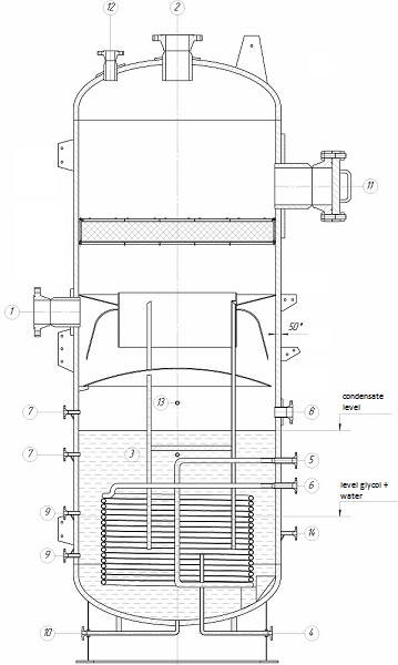
Figure 2 – Separator: socket 1 – The gas inlet, 2 – out of gas, 3 – condensate yield, 4 – Output glycol + water, 5 – exit glycol, 6 – entrance glycol 7, 8, 9 – transmitter, 10 – purge, 11 – hole 12 – Safety valve, 13 – pressure gauge, 14 – thermometer.
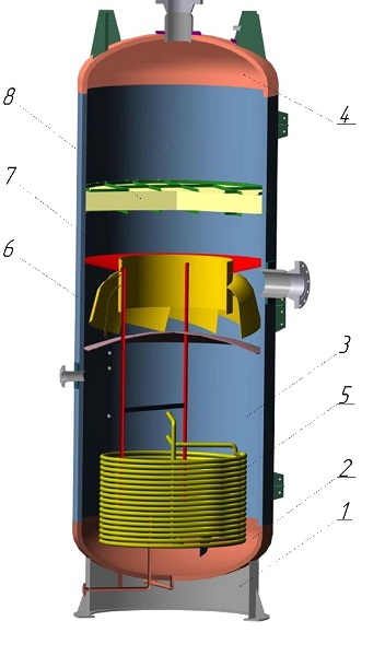
Figure 3 – Separator: 1 – support ring, 2 – bottom elliptical, 3 – housing, 4 – cover elliptical, 5 – serpentine, 6 – bump, 7 – primary separation section 8 – kapleulavlivatel
Nozzle separators [3].
There are many different designs of cages, but the weight they usually consist of a main section of the separation, settling, liquid collecting section and kapleulavlivaniya.
main separation section. It is intended to separate the main of the liquid (oil, condensate, water) from entering gas–liquid flow. To ensure effective pre– separation and uniform flow distribution over the cross section apparatus use of different types of structural unit.
tangential inlet flow should discard the liquid under a centrifugal force to the vessel wall. The liquid flows down and the gas is distributed over the cross section of the apparatus and discharged him. Various reflective device (or a rectangular plate circular, hemispherical) mounted at the inlet of the separator.
Settling section. In this section, in gas–oil separators is further effervescence of oil. In gas Fluid separators in this section is separated by the action of gravitational forces, the gas moves in a vessel with relatively low speed. In some designs of gas separators to reduce turbulence using various devices: plate, coil and a semicylindrical surface. In the gas–oil separators the intensification of the process of allocating free and dissolved gas oil is used in a tilted plane. In this case, the flow of oil should smoothly without splashing merge into the bottom of the separator.
Liquid collecting section. This section is intended to collect the liquid, which in previous sections almost completely separated from the gas. However, some gas left in it. For separators which separates the gas and light hydrocarbons contained in the liquid phase volume of this section is selected so that it is possible to hold the Separated liquid during the time required for the output gas bubble to the surface and entering the secondary gas flow.
Section kapleulavlivannya. The purpose of this section – capturing liquid particles in the outgoing gas from the separator. Section usually consists of pneumatic nozzles of different types: ceramic rings packet woven wire mesh and other criteria separation efficiency dropping liquid from the gas is the value of specific entrainment, which should be in the range of 10 – 50 mg/m3 gas. The effectiveness of the pneumatic nozzle depends on the speed limit gas flow, the amount of fluid coming from the gas; uniformity packing loading at the cross–sectional area thereof.
In addition to the functions performed by the listed sections and structures separators include elements foamsuppressing and extinguishing it, and reduce the harmful effects of pulsation gas–liquid separation in the flow of oil and gas. prevention Ripple is especially true for gas–oil separators, installed in oil gathering system.
Section final purification are usually located in the upper of vertical separators and spherical. In the horizontal Section separators final cleaning is at the opposite from the inlet end. Section fluid collection is usually spherical bottom and vertical separators. In the single–cylinder horizontal separator liquid is from 1/3 to 1/2 the bottom cylinder. In horizontal twin–cylinder separator according to structures for this purpose the half to the total volume lower cylinder.
Vertical separator has certain advantages over the Other types of separators, if the gas stream contains many solids, a hook as it has good drainage and is easy to clean. These separators require less space for installation. however significant height of vertical separators when used in Mobile or large–performance installations creates serious difficulty in their assembly and operation [4].
This machine was developed in an environment COMPASS. One of the most difficult details were petals on the turbulators. They have a complex structure, and their shape is changed in all planes, which was difficult as close as possible to build their model. The model is constructed using constructing points of a cylindrical surface and then were joined composite curve and shape of the trajectory and with kinematic operations were built petals [5].
3.2 Computer Simulation
3.2.1 Choosing software for solutions
To solve the problems, there are many programs that use Various methods. Among them are leading two – SolidWorks Flow Simulation and COMSOL Multiphysics, using the method for calculating finite elements. Due to the fact that SolidWorks Flow Simulation has a number of advantages: support the imported geometry, has a multi–core calculation mode and preview mode results, we stayed on it [6].
3.2.2 Method of calculation.
The solution of the problem in SolidWorks Flow Simulation is performed in three stages. The first step is the creation or import models and assemblies on the second phase, the proper modeling of the problem, and the third – the processing and display of results.
The object is internal, that is, the movement of gas modeled confinement where space is limited and the input outlets and the walls of the model. This type is suitable for decision problems associated with gas flow in the piping, valves, taps, heat exchangers, etc. [7].
3.2.3 Simplifying the model and export of geometry
3D modeling was performed in CAD KOMPAS–3D. The model was built in a three–dimensional assembly, the appearance of which the maximum approaching the actual appearance of the object. Separator model was simplified because they merely add a computational grid, which results in an increase in the estimated time without significant impact on the result calculation.
After simplification, there is only the inside of the machine, ie primary separation section, bump and kapleulavlivatel. Summary separation section and the baffle changes have been made, and the author kapleulavlivatele been thoroughly cleaned mounting system .. were also dropped some technological aspects – pipes, fittings and etc., which have no significant effect on the movement (Fig. 3).
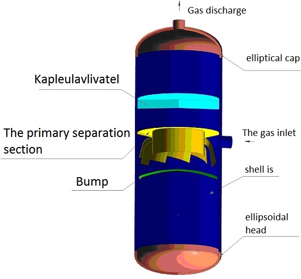
Figure 3 – A simplified model of the separator
To export geometry using the format (*. x_t), which supported by most CAD systems. The result is a model of the assembly and the corresponding tree model project build [7].
3.2.4 Create covers and check the geometry
To create a closed space is required to close the hole special objects – covers. After creating a closed the amount necessary to check the geometry for errors that could arise when exporting. When checking the calculated volume of the gas–liquid mixture of solids and [7].
3.2.5 Making porous body
The main problem in the simulation of flow in such systems is the radial extent of the difference. In COSMOSFloWorks for objects with Such differences scales used family settings Narrow Channel (narrow channel), but the number of long perimeter mantle gaps of several million. It is therefore necessary to use such an entity as a Porous Medium (porous body), which is a "homogenized" model of heterogeneous media, formed by periodic objects. COSMOSFloWorks contains several types of porous media [8].
In our case, the porous body, called Verkstof (Fig. 4) projected and calculated separately. Key Features porous body: isotropic, which has the same permeability to all directions.
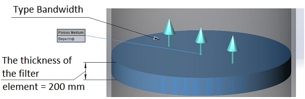
Figure 4 – Porous body
Simulating the porous material porosity was calculated by k characteristic directions (Fig. 5).
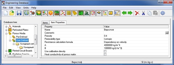
Figure 5 – Table of characteristics of the porous body Verkstof
3.2.6 Create a Project
Creating a project is executed by using the Wizard. The first step in the configuration we set the project name. On the second – the window choice of ischesleniya was chosen SI system. At the third stage – Window type of analysis, which takes into account the forces gravity, speed and time, in this case, the host power gravity. In the fourth step, choose the working environment. In this If the work environment, ie natural gas and crude petroleum condensate designed yourself, as they depend on the field. On the fifth – the parameters of the wall for the thermal problem, the sixth step – a window of internal conditions: pressure, temperature, turbulence parameters, chosen pressure P = 6900000 MPa, temperature T = 10° C. At last – the quality setting nets [8].
3.2.7 Setting the boundary conditions and the performance of the calculation
to bind to a specific mathematical model of an engineering problem you must set the boundary conditions. In the case of stationary solutions tasks typical conditions completely determine the distribution of flows fluid. When making domestic tasks, the input (Intel) and Weekend (Outlet) streams flow boundary conditions, and the conditions on selected model surfaces that come in contact with the medium [9].
To set the boundary condition, call the Insert Boundary Condition from the contextual menu of the Boundary Condition project tree calculation. In the window that opens, choose the face and ask the corresponding condition (Fig. 6).
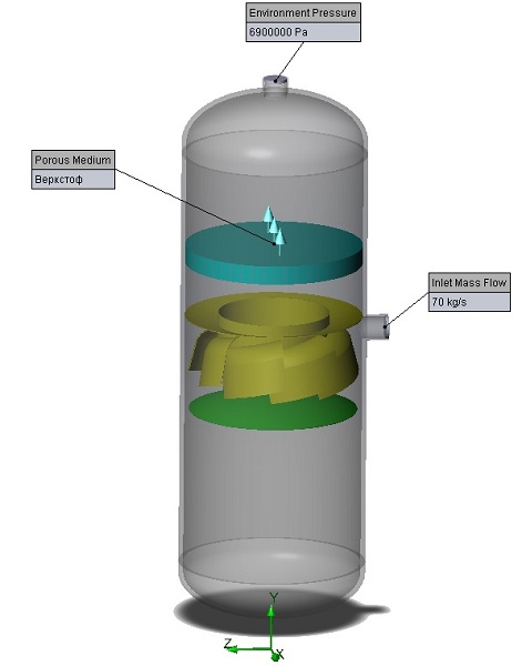
Figure 6 – The boundary conditions of the problem
The task starts at the expense of the team Run. After you run calculating the settings window where you can specify the number of processors and computers on the network used for the calculation. also customizable generation of the computational grid and the start of calculation with using the previous results.
After the calculation can be obtained by a number of results, such as: flow characteristics of gas–liquid mixtures in different sections of the trajectory traffic flow parameter values °°in any point or volume the computational domain. Below are some illustrations of the results calculation (Fig. 7).
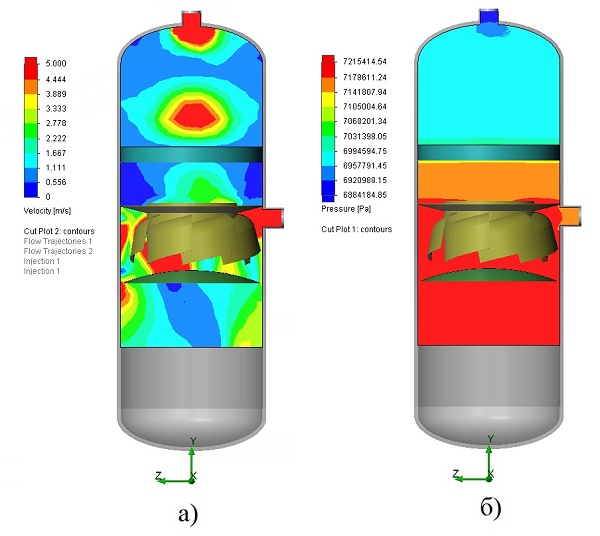
Figure 7 – Results of aerodynamic calculations the cold separator second stage (a – distribution speed on the machine, b – pressure distribution over the wire)
Proposals to improve the efficiency of the cold separator second stage
To improve the cold separator proposed The following technical solutions:
• tangential inlet gas–liquid flow:
o tangential inlet gas–liquid mixture;
o double tangential inlet gas–liquid mixture;
o triple tangential inlet gas–liquid mixture;
• varying the height of the main section of the separation.
All proposed designs apparatus shown in Figure 8.
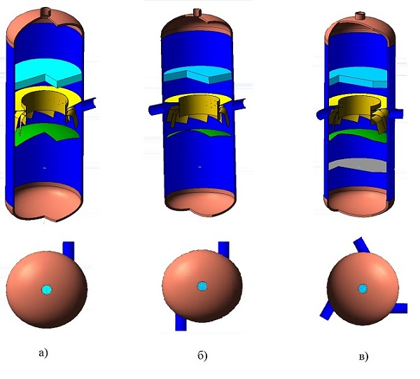
Figure 8 – The proposed construction of the separator (a – tangential inlet gas–liquid mixture, b – double Tangential entry of gas–liquid mixtures in – triple tangential inlet gas–liquid mixture)
As the results of the calculations of the proposed designs machine represents the most rational design – tangential inlet gas–liquid mixture. Since the efficiency of separation is achieved in this design is 99%. The results of the calculation are shown in Figure 9 and 10.
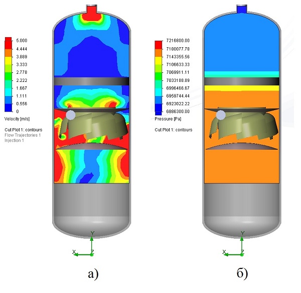
Figure 9 – The results of aerodynamic calculations the second stage of the cold separator (a – velocity distribution on the machine, b – pressure distribution over the wire).

Figure 10 – Trajectory of the gas flow (animation: the size of 288 kb, 5 shots, 5 reps, the delay between frames of 0.5 seconds.)
Conclusion
Thus we can conclude that structure analysis cold separator second stage, and the results of computer gas dynamics simulation of the separation process revealed a number of material weaknesses and areas for further substantiate research and development.
Known design has low cold separator separation efficiency due to a bad input gas stream.
Increase the separation efficiency achieved by changing the input stream liquid mixture.
At the moment, master thesis is to be written. Final completion: January 31, 2013. Full text of the work and materials on the topic can be obtained from the author or his manager after that date.
References
- Руководство по добыче, транспорту и переработке природного газа / Катц Д. Л., Корнелл Д., Кобояш Р.Н., Поеттманн Ф.Х. — — М.: Недра, 1965. – 677 с.
- Технологические процессы подготовки природного газа и методы расчета оборудования / Ланчаков Г.А., Кульков А.Н., Зиберт Г.К. — М.: Недра–Бизнесцентр, 2000, 279с.
- Оператор по добыче природного газа / Задора Г.И. — Ростов н/Д: Москва: Недра, 1980. – с.250
- Переработка природного газа и конденсата / Мишин В.М. — М.: Издательский центр "Академия", 1999. – 448 с.
- Руководство пользователя КОМПАС 3D V13 / Кривцов Д.И. — ЗАО АСКОН
- SolidWorks Simulation как решать практические задачи / Алямовский А.А. — СПб.: БХВ–Петербург, 2012. – 449 с.
- SolidWorks Simulation компьютерное моделирование в инженерной практике / Алямовский А.А. — СПб.: БХВ–Петербург, 2008. – 1040 с.
- Инженерные расчеты в SolidWorks Simulation / Алямовский А.А. — СПб.: БХВ–Петербург, 2010. – 235 с.
- SolidWorks. Компьютерное моделирование в инженерной практике / Алямовский А., Собачкин А., Одинцов Е., Харитонович А., Пономарев Н. — СПб.: БХВ–Петербург, 2005. – 800 с.