Abstract
Contents
- Introduction
- 1. Relevance of the topic
- 2. The goals and objectives of the study
- 3. Review of existing lathes and machining technology conical surfaces
- 3.1 Review of existing varieties lathes
- 3.2 Radiometric scheme that allows to control the wall thickness of the workpiece
- 4. The algorithms of the device
- 4.1 The algorithm checks the integrity of the product
- 4.2 The algorithm processing products
- Conclusion
- List of sources
Introduction
Now manufacturers are trying to limit the manual labor and possibly reject it - instead of people are beginning to work the machine. Indeed, technology does not stand still, the equipment allows to produce work more accurately and with a smaller percentage of marriage. Moreover, many types of work, which lasted a long time before now run machines with stunning accuracy and in a very short period of time.
Accordingly, the automation of production is an important task for any company that is in step with the times, but this process is not always smooth and easy. For best results, have to apply new methods and scientific development. The process of modification and integration of information system sometimes becomes difficult and expensive task, but with the right approach in most cases the implementation of ACS significantly improves production.
1. Relevance of the topic
Currently, workpieces of complex shape with precise control of the wall thickness in the product consists largely of manual work as a master must remove the workpiece from the lathe and produce corresponding measurements micrometer. This substantially increases the production time of one detail, as the method is not reliable in terms of human factor - master measurements may mistake. With this method, there is a greater likelihood of marriage – the processing of the product master can not choose the right time when treatment should be stopped, as a consequence, increases the likelihood of marriage in the workplace.
These reasons make it necessary to automate and control the workplace.
2. The goals and objectives of the study
The purpose of the master's work is the development of an automated control system with a radiometric system.
In the course of the work is expected to perform the following tasks:
1. An analysis of existing methods of processing products;
2. Select lathe and radiometric system suitable for automation task;
3. Simulation of the wall thickness measurement items;
4. Development of the algorithm checks the integrity and homogeneity of the workpiece by means of EHF electromagnetic radiation;
5. Developing an algorithm of the automated milling machine that can handle the workpiece to the desired thickness value;
3. Review of existing lathes and machining technology conical surfaces
Today, there are several types of lathes designed for machining of various types and have different performance. They can also be divided into automated and computerized machines.
3.1 Review of existing varieties lathes[1-3]
Lathes, depending on their structures and functions are divided into types[1]:
- Screw-cutting lathe;
- CNC turret lathe;
- Table lathes;
- Vertical lathe;
- Automatic sliding head;
- CNC machines.
Various machines perform specialized tasks, but for industrial automation blanks conical most suitable screw-cutting lathe with CNC[3], since such a machine already incorporates a programmable logic controller, which allows the processing of items according to a given program.
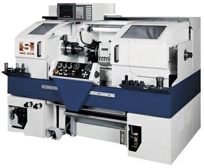
Figure 3.1. – Screw-cutting lathe with CNC
However, this machine does not allow the evaluation of the wall thickness of the product[4], respectively, it must be supplemented by a system capable of producing the necessary measurements.
3.2 Radiometric scheme that allows to control the wall thickness of the workpiece[5]
This system is used for non-destructive testing of technological parameters of objects which are determined by the change in the phase of reflected electromagnetic waves EHF. This will control the wall thickness of articles automatically with a high accuracy.
In a radiometric measurement system for the wall thickness working parts antenna for both transmission and reception signal is measured by one, the number of antennas is determined by the characteristics of the product – the product is more – the more antennas are required for accurate measurement (necessary that the entire surface of the article fell in the radiation field antennas).
Figure 3.2 shows the location of the antenna relative to the product
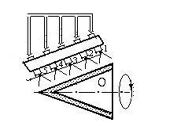
Figure 3.2. – Location of the antenna relative to the product
Figure 3.2 numerals 1-5 identified antenna aimed at the outer surface parts (products).
Management of the transmission and reception of signals from the antenna, as well as their switching performed by the controller of the CNC machine.
Fully radiometric scheme is shown in Figure 3.3
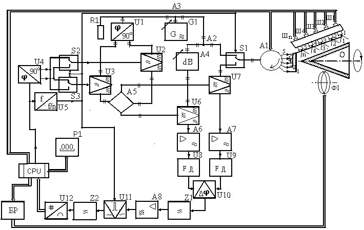
Figure 3.3. – Radiometric scheme
The circuit comprises a generator G1 harmonics EHF-band power dividers A2 and A3 are connected to the generator G1, automatic switch S1 and A1 circulator connected with receiving and transmitting antennas 1 - n, fixed to the corresponding moving stocks W 1 - W n , located on the bracket, which follows the shape of the product and directed to the monitored, A4 matching attenuator is connected to the other output of the power divider A2 EHF-balanced mixers U6 and U7, the outputs of which are connected serially connected intermediate-frequency amplifiers A6 and A7, Formers short pulses U8 and U9 and U10 linear phase detector flip-flop. To the second output of the power divider is connected A3 EHF quadrature fazodelitel U1, the outputs of which through EHF-balanced modulators U2 and U3 is connected magic tee A5, the outputs of which are connected to the other inputs of EHF-balanced mixers U6 and U7, low frequency oscillator, a built-in microcomputer cpu and connected to the low-frequency quadrature fazodelitelem U4, which outputs via automatic switches S2 and S3 are connected to the baseband inputs EHF-balanced modulators, U2 and U3. U5 frequency divider circuit connects the control inputs of the switches S2 and S3, and the low-frequency oscillator output, built-in microcomputer cpu. To trigger the output of phase detector U10 is okay series connected high pass filter Z1, low frequency amplifier A8, synchronous detector U11, lowpass filter Z2, analog to digital converter U12, cpu microcomputer and digital indicator P1. The control input of the synchronous detector U11 is connected to the control inputs of the automatic transfer switches S2 and S3. The digital output is connected to a microcomputer cpu kodoupravlyaemym Control Unit (BR) mode of machining products mill F1.
4. The algorithms of the device
4.1 The algorithm checks the integrity of the product[6]:

Figure 4.1. – The algorithm checks the integrity of the product
A1c – the initial value of the attenuation coefficient of 1st attenuator
А2с – initial value of the 2nd attenuator
Uцел – target value of the absorption coefficient
U[i][j] – absorption coefficient at a given point
Af[i][j] – deviation value of attenuation coefficient 1st attenuator at a given point
ε – tolerance of the absorption coefficient
A1 – the current value of the attenuation coefficient attenuator A1
r – mode of the device
t – current temperature of the product
tc – target temperature of the product
Lцел – target value of the radiation facility
L[i][j] – value of emissivity of the object at a predetermined point
As[i][j] – the value of the damping coefficient 2nd attenuator at a given point
ε1 – tolerance radiation facility
A2 – the current value of the attenuation coefficient attenuator A2
First, there is the input reference values and tolerances and the target temperature. Further there is a measurement of the absorption coefficient. If the signal is different from the standard - changing the value of decay kodoupravlyaemogo attenuator A1 as the value does not match the reference. The amount of change of attenuation coefficient A1 and coordinates the radiation zone are stored computer.
Next comes the construction schedule for a set of absorption coefficients of the material across the surface of the product (the output of the absorption coefficients and changes in attenuation coefficients A1). Then the system switches to a different operating mode.
Produced heating of the material to a predetermined temperature and maintaining it throughout the second mode of measurement. Then there is the measurement of radiation. If the input signal is different from the reference, at the attenuator A2 signal is amending its decay to a value corresponding to the reference signal value The measurements are also recorded and plotted (the output values of the radiation attenuation coefficient A2 at all points).
Further there is a comparison of the first and second modes of operation and with reference values. (Another finding factors that do not meet the standard).
Places where the coefficients do not correspond to the reference are suspicious of marriage.
4.2 The algorithm processing products[7]
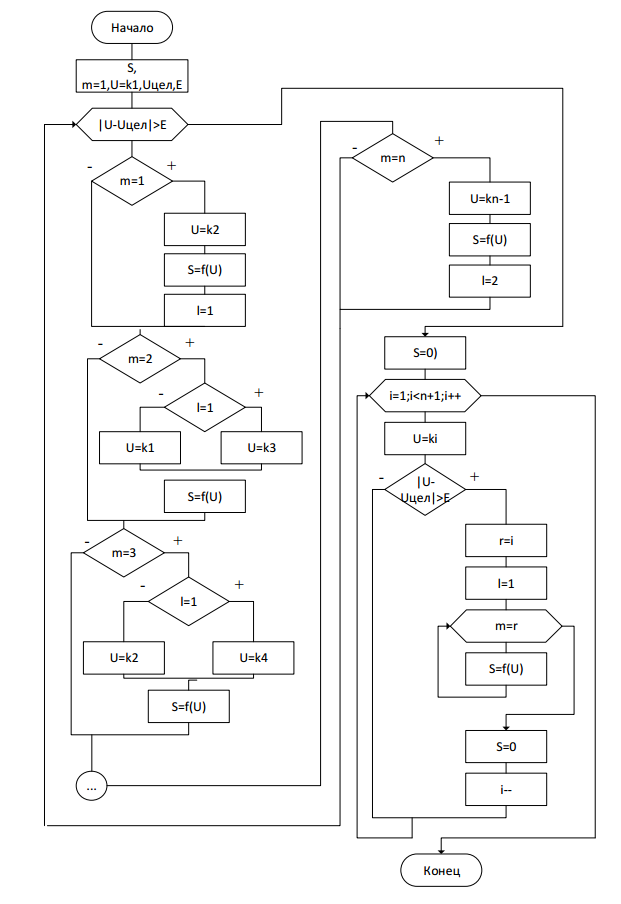
Figure 4.2. – The algorithm processing products
In developing the algorithm were used such symbols:
m – cutter position relative to the reception area of the reflection;
S – the depth of the cutter feed;
U – the current value of the phase of the probe signal;
Uцел – target value of the phase of the probe signal;
E – allowable phase difference sounding signal according to a predetermined value of thickness of the workpiece;
массив k – phase values of the probing signal from antennas (the number of elements in the array equals the number of antennas);
l – direction of the cutter;
r – controlled position relative to the antenna (1–n).
Measurement of produced ahead (coefficient measured before the mill).
When the number of transmitting antennas equal n, the product is divided into n zones, which may be milling. Current status variable corresponds milling m, at the beginning of the program is located at the beginning of the milling product, m = 1, respectively. Also at the beginning you must specify the target value of the phase of the probe signal, which we will strive in processing products and E - allowable phase difference, according to the specified value of the wall thickness, it will be used to determine the completion of the processing of the product. The current value of the phase of the probe signal is determined by the testimony of the antenna.
Until another condition | U-Utsel |> E, performed machining products. The product is processed according to the current value of the phase of the probe signal U (adjusted depth of the cutter feed). The current value of the phase of the probe signal U is determined by the position ahead of cutter - if cutter is in the first receiving area, signal reflections - phase current value of the probe signal is taken from the 2nd antenna, U = k2, calculated feed milling depth S = f (U) , milling direction is set to 1, l = 1 if the cutter is in the second zone and the direction of the antenna is taken from the cutter 3, U = k3, if the direction of cutter is not equal to 1, the current phase value is taken from the antenna 1, U = k1, calculated feed milling depth S = f (U), is carried out analogously to determine the current value of the phase of the probe signal and the depth of the cutter feed until the n-th area when finding milling in the n-th zone, m = n, the current phase value taken from antennas (n-1), U = kn-1 calculated feed milling depth S = f (U), the direction of cutter set to 2, l = 2.
When it reaches the condition | U-Utsel |> E, machining products stops, S = 0. Next, you must check in each zone to achieve the desired result. For this work cycle i = 1; i
At the end of the algorithm required accuracy is achieved in all areas of n .
Radiometric work scheme can be seen in Figure 4.3
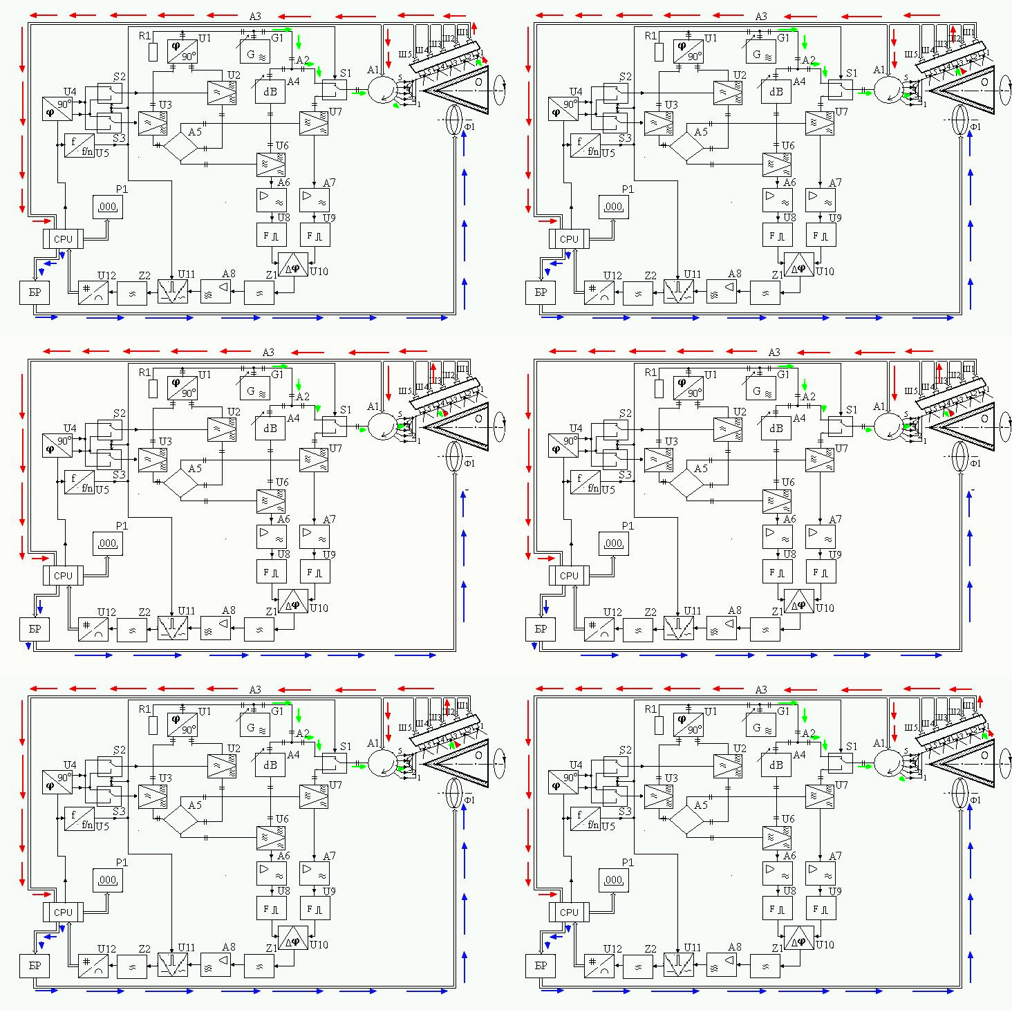
Figure 4.3. – Radiometric work scheme
Conclusion
On the basis of the goals and objectives were to analyze different types of milling machines and machining of complex shapes. Was chosen the most suitable type of machine automation, considered radiometric system, which allows for non-destructive testing products have been proposed algorithms for checking the integrity and homogeneity of the workpiece by means of EHF electromagnetic radiation and operation of automated milling machine that can handle the workpiece to the desired value of the thickness.
In writing this essay master's work is not yet complete. Final completion: December 2014. Full text of the work and materials on the topic can be obtained from the author or his manager after that date.
List of sources
- Модзелевский А.А., Мущинкин А.А., Кедров С.С., Соболь А.М., Завгородний Ю.П. Токарные станки / А.А. Модзелевский // Машиностроение. – 1973. – 282с.
- Фещенко В.Н. Токарная обработка / В.Н.Фещенко – Высш. шк. – 2005. – 303 с.
- Панов Ф. С., Травин А. И. Работа на станках с числовым программным управлением / Ф.С Панов. – Л.:Лениздат – 1984. – 278с.
- Головко Д.Б., Скрипник Ю.О., Яненко О.П. Надвисокочастотні методи та засоби вимірювання фізичних величин. / Д.Б. Головко – К.: Либідь, 2003. – 328 с.
- Куценко В.П., Скрипник Ю.А., Трегубов Н.Ф., Шевченко К.Л., Яненко А.Ф. Методы и средства сверхвысоко-частотной радиометрии / В.П. Куценко – Донецк: ИИиИИ «Наука і освіта», 2011. – 324 с.
- Звіт про виконання науково-дослідної роботи „Розробка алгоритмів оптимального управління системами неруйнівного контролю в умовах технологічних процесів виробництва продукції на ККНВП „Кварсит” — Донецк: ДонНТУ, 2012. – 92 с.
- Довгопол В.А., Куценко В.П. Разработка алгоритма работы радиометрической системы контроля параметров диэлектрических изделий. / В.А. Довгопол – Матерiали IV мiжнародної науково-технiчної конференцiї студентiв, аспiрантiв та молодих вчених. — Донецьк, ДонНТУ — 2013, Том 1, с. 533–537.
