
Abstract
Contents
- Introduction
- 1. Theme urgency
- 2. Goal and tasks of the research
- 3. Virtual Model of Real-Time System
- 4. Development of measurement and data analysis system that is implemented on the FPGA board Xilinx Spartan-3E
- Conclusion
- References
Introduction
Real-time systems (RTS) are complex hard- and software systems that responds to the expected time for the unpredictable flow of external events. RTS must able to respond to the specific event, which occurred in the technological object, in interval of time which value is determined by the object and the event may be different, but the response time of the system must be provided at the design stage of system. The lack of reaction in the envisaged time is a mistake for real-time systems, in addition the system should react to events which are occurring simultaneously. Even if two or more external events occur in the same time, the system must react to each of them during the time intervals that are critical for these events.
In this work the model of RTS and the hardware realization of it will be complete with help of LabVIEW – the system design platform and development environment for visual programming language from National Instruments, which commonly used for data acquisition, instrument control, and industrial automation on a variety of platforms including Microsoft Windows, various versions of UNIX, Linux, and Mac OS X.
1 Theme urgency
Real-time systems – an extremely important area of modern technology. Nowadays all automated systems that affect our life and health are real-time. The role of these systems is growing as more as engineering processes being studied with sufficient depth to automate.
However, developing such systems is usually difficult task that requires significant time and material costs. In addition, the developed system is usually inflexible and is intended to process a narrow range of tasks without the possibility of system’s short term rebuilding under the new technical requirements.
2 Goal and tasks of the research
The purpose of this master's work is the elaboration of automation, high effective techniques of development of different tasks real-time systems and reduce the cost of their implementation. To this end, the work proposes the use of FPGAs and specialized development environment LabVIEW, which together offer a broad engineering capabilities.
On the one hand using the programming language G can explicitly specify the hardware structure of the system which is being developed, streaming programming provides easy realization of parallel executable block operations and a rich library of built-in operators which all can help system designer concentrate on implementation of the main task. All this leads to less time of system design than by using classical methods of such systems developing (VHDL, C, Assembler, Matlab etc.).
Using FPGAs to implement real-time systems or systems opens up the possibility to use only one physical device for many practical, scientific and research purposes, as reprogramming the FPGA for realization of new task in the presence of ready-made solution takes seconds.
So here are the research tasks of this work:
- Analysis and research of streaming programming language G methods in LabVIEW;
- Research of work with LabVIEW FPGA toolkit;
- Research of different configurations of RTS model;
- Development of methodics for usage the LabVIEW FPGA toolkit to configure FPGA-boards;
- Testing of developed solutions in laboratory practice and in close to production conditions.
The expected result is developed virtual model of the real-time system and comprehensive system of data collection and analysis which consist of FPGA-measurement node and host-PC with GUI that are connected by the USB-interface.
3 Virtual Model of Real-Time System
Developing of real-time system model implements some important tasks:
The main component of multitask RTS is supervisor. To perform its functions, it handles problems with parameter of frequency, defined by a system timer. Since the supervisor must realize penal sanction to a task, which exceeds its maximum execution time, and stop its execution, the supervisor must pass control to task in the queue for execution at the time of removal of the current task, rather than through tact. So supervisor should work with a greater frequency than the tasks execution frequency. In a system that developed, Δtsyst equal to 1 second, because the model is used to test main principes and algorithms and implemented in the operating system MacOS based on the core-UNIX, which is not real-time system. Supervisor also works with an interval of 0.1 second, which ensures implementation of functions, that were mentioned above.
According to its functionality, there are three logical units of supervisor functions that implement these capabilities:
Supervisor does not respond to external events directly. Therefore, a necessary component of task planning system is the unit of primary event handlers. Primary handlers identify events from external system devices (which simulated by keyboard and mouse – with these user can appropriate interrupt in random time) and form the corresponding flags in the flags field, which are processed by the task manager. It was mented earlier that imitation model of RTS designed with help of LabVIEW. LabVIEW programm named virtual instrument (VI). VI consist of four parts: front panel, block-diagram, icon and connector pane.
The block-diagram of supervisor consists of four algorithm frames:
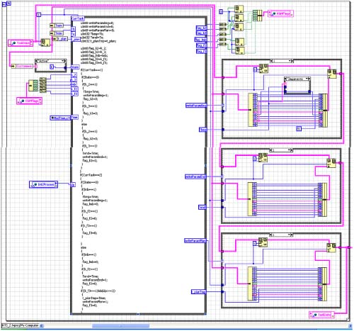
Figure 1 – Block-diagram of the first algorithm’s frame
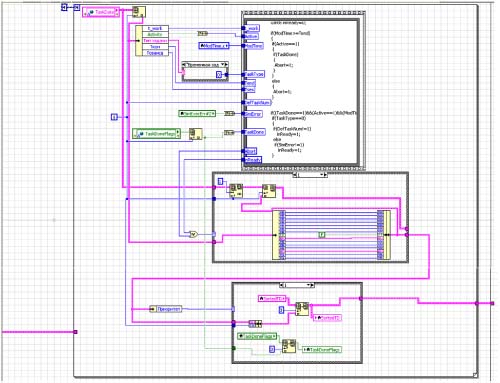
Figure 2 – Block-diagram of the second algorithm’s frame
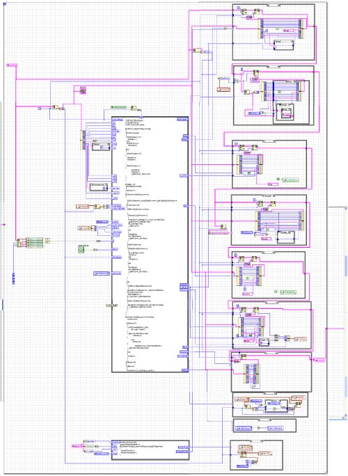
Figure 3 – Block-diagram of the third algorithm’s frame
4 Development of measurement and data analysis system that is implemented on the FPGA board Xilinx Spartan-3E
The next stage of the master's work provides a hardware implementation of real-time system on FPGA-based solution using toolkit LabVIEW FPGA. The main advantage of measurement and analyzing data solutions built on FPGA is possible rebuilding of system so such flexible platform can cover a wide range of tasks, from data measurement and storage and complex analysis algorithms to high rate control in the scale of nanoseconds.
The real-time system which based on FPGA, can solve tasks such as on-board data measurement, noise and vibro-acoustic analysis, equipment control. Autonomy of such a system is in demand in many scientific and industrial projects:
- Measurment and processing – high speed movement control, batch process control, discrete control;
- Heavy machines control – processing signals in real-time and power electronics and hydraulic systems control;
- Semiconductor and biomedical industry – specific movement control and image processing, control of raw material supply;
- Equipment monitoring – analysis of wearout, cooling control, lubricant presence, etc.;
- Mobile / portable system of noise and vibroacoustic analysis – analysis of noise, vibration, dynamic signal analysis;
- Distributed measurement – central controller with distributed IO nodes connected through wired or wireless networks.
Such a system typically has a architecture that consists of three processors: a computer running Windows, one in the real-time controller and the FPGA core. National Instruments FPGA solutions have very good features and are perfect for industry designs but they are very expensive, fortunately there is an opportunity to use the board Xilinx Spartan-3E, which is recommended by National Instruments to perform non-commercial projects of education institutions. Since the board Spartan-3E, in contrast to the series CompactRIO, has not onboard real-time controller, predictable structure of system which is being developed, includes a host processor station and the core FPGA.
The logic, functions of input-output, timing and synchronization, triggering implemented in FPGAs in hardware and is completely determined by the user during a configuration. The core of the FPGA directly connected to IO modules that ensure the accuracy and flexibility of timing, triggering and synchronization. IO modules contain built-in pre-processing of signals, ADC and DAC converters. Data between the FPGA and the modules are transmitted in digital form.
It is assumed that a hardware module on FPGA receives and collects information from the sensors with a given frequency, periodically sending packets of information by USB-interface to the host application on a personal computer, which visualizes the obtained data, stores them in a log-file and provides the information interaction with user through a graphical interface.
Figure 4 shows the work illustration of system which is being developed.
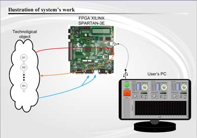
Figure 4 – Illustration of system's work
This master's work is not completed yet. Final completion: December 2013. The full text of the work and materials on the topic can be obtained from the author or his head after this date.
References
- National Instruments – Developer's Zone [Электронный ресурс]. – Режим доступа: http://zone.ni.com/dzhp/app/main.
- NIDays08 – Worldwide Graphical System Design Conference [Электронный ресурс]. – Режим доступа: ftp://ftp.ni.com/pub/branches/uk/nidays2008/NIDaysBooklet.pdf – pp. 31-34, 41-42, 46-47.
- Rick Bitter, Taqi Mohiuddin, Matt Nawrocki. Advanced Programming Techniques, Second Edition – Boca Raton: CRC Press, 2006. – 500 p.
- Cory L. Clark. LabVIEW Digital Signal Processing and Digital Communications – New York: McGraw-Hill, 2005. – 205 p.
- Kenneth L. Ashley. Analog Electronics with LabVIEW – Upper Saddle River, NJ: Prentice Hall, 2003. – 432 p.
- Деcятая международная научно-практическая конференция. Инженерные, научные и образовательные приложения на базе технологий National Instruments 2011 [Электронный ресурс]. – Режим доступа: http://www.labview.ru/Conference2011/Sbornik%20trudov%20konferencii%202011%20electr.pdf – pp. 245-246, 268-273.
- Мищенко С.В., Дивин А.Г., Жилкин В.М., Пономарев С.В., Свириденко А.Д. Автоматизация измерений, контроля и испытаний – Т.: издательство ТГТУ, 2007. – 116 с.
- Бутырин П.А. Автоматизация физических исследований и эксперимента: компьютерные измерения и виртуальные приборы на основе LabVIEW 7 – М.: ДМК Пресс, 2005. – 264 с.
- Шалыто А.А. Логическое управление. Методы аппаратной и программной реализации – СПб.: Наука, 2000. – 780 с.
- Федосов В.П., Нестеренко А.К. Цифровая обработка сигналов в LabVIEW – М.: ДМК Пресс, 2007. – 456 с.
- Мещеряков С.Д. Цифровая обработка сигналов с помощью платы АЦП и программного комплекса LabView – М.: Московский государственный университет им. М. В. Ломоносова, 2004. – 44 с.
- Тесленко В.А. Подключение датчиков к ПК. Учебный практикум – К.: НТУУ "КПИ", 2004. – 7 с.
- Денисенко В.В., Халявко А.Н.Термометры сопротивления, Термисторы и Термопары. Учебный практикум – Таганрог: НИЛ АП, 2004. – 5 с.
- Уроки по LabVIEW [Электронный ресурс]. – Режим доступа: http://www.picad.com.ua/lesson.htm.
- Волошин Д.Н. Разработка системы реального времени на базе Xilinx XC3S500E Spartan-3E FPGA. – Інформатика і комп’ютерні технології (ІКТ-2011) / Матерiали VII мiжнародної науково-технiчної конференцiї студентiв, аспiрантiв та молодих вчених – Донецьк, ДонНТУ – 2011, с. 44-47.