
Abstract
Содержание
- 1. Relevance of a subject
- 2. Purpose and problems of a master's thesis
- 3. Summary of results of a master's thesis
- 3.1. Short data on mine
- 3.2. Ways and means of fight against a dust
- 3.3. Preliminary coal moistening in an array
- 3.4. Irrigation during the operation of the extraction combine
- 3.5. Irrigation on loading point of a clearing face
- 3.6. Irrigation during the operation of prokhodchesky combines
- 3.7. Shale barriers
- 3.8. Water barrier
- 4. Measures for the prevention and containment of coal dust explosions
- Conclusion
- References
1. Relevance of a subject
Modern ways of underground coal mining it is characterized by formation of a significant amount of a dust with its transition to a suspension and the subsequent adjournment on walls of excavations. The dust is dangerous not only as an explosion source, but also as a source of occupational diseases.
In work actions for decrease in a dust content on an extraction site in a preparatory face of m3 layer of mine of V. M. Bazhanov are chosen. Therefore it is important to create necessary actions for elimination of a coal dust.
2. Purpose and problems of a master's thesis
Main goal is decrease in a dust content of air.
For achievement of this purpose it is necessary to decide the followings tasks:
- To estimate efficiency of dust actions on mine.
- To develop the complex of measures on the decline of dust-ladenness of air.
- To carry out the analysis of modern ways and means on a complex obespylivaniye of mine air.
3. Summary of results of a master's thesis
3.1 Short data on mine
The mine of V. M. Bazhanov is located in the northeast of the city of Makeyevka of Donetsk region. Economically the mine is located in the area with well developed metallurgical and coke–chemical industry and an advantageous position in relation to railway lines and the main consumers of being coked coals. In northern part of a mine field pass railway lines of Yasinovataya – Krinichnaya – Ilovaysk, Yasinovataya–Makeyevka. These lines are adjoined by access roads of mine of V.M. Bazhanov, Jasinowski of koksokhimzavod, steel works of a name of Kirov.
The mine of V.M. Bazhanov is constructed according to the Yuzhgiproshakht institute project with design capacity of 1200 thousand tons of coal a year. Construction of mine was begun in 1952. The project provided mine construction in two turns. The first stage is put in operation in 1957 with design capacity of 400 thousand tons per year with working off of stocks of n1в and n1н layers on the horizon 195 m. The second turn is put in operation in 1964 with design capacity of 800 thousand tons of coal a year with working off of stocks of m3 layer on the horizon 1012 m.
In 1989, by order of the Minister of Coal Industry of the USSR of 09.27.89, the number 138 in connection with working off the main industrial stocks on layers n1v–n1n capacity of the 1st stage of the mine in the amount of 420 thousand tons of coal per year written off since 1992. Since then, the production of the mine ranged from 1000–1200 tons per year, with installed capacity of 1,050 tons of coal a year.
3.2 Ways and means of fight against a dust
In accordance with the "Instruction ..." [2, 7] in the working face should be taken complex anti–dust measures, including pre–wetting of coal in the array, irrigation at the loading point stope, dust control during drilling, excavation of coal and rock hammers, loading coal in the niches, and dust control in the development workings.
3.3 Preliminary coal moistening in an array
For drilling holes used hand–held e–mail. Drill SR-19D. The injection of water into the coal produced by an array of high–pressure setting EN. Through holes are drilled from the stope throughout.
Holes are drilled middle seam thickness. The distance between the hole 5m germitizatsiya holes by means of seal water (Turusov
). Germitizatsiya hole not mnee 2.5 m
Figure 1,2 – Flowsheets of festering of water from the preparatory making in the cleansing backwalls of declivous layers (a) and at a shield coulisse on steep layers (b)
(animation – 7 frames, 5 cycles of repetition, 132 kilobytes)
(1 – a valve; 2 –a filter a drift; 3 – a metering device of smachivatelya; 4 – a flowmeter; 5 – the pumping setting high-pressure; 6 – a drift pipeline; 7 – germetizator; 8 – a boring machine-tools)
Wetting dB (0.2 % concentration) is added to the water centrally. The effectiveness of pre-wetting of 60 %. [6]
3.4 Irrigation during the operation of the extraction combine
According to the instructions for the integrated dedusting, the specific consumption of water for irrigation when working shearer 1GSH accept 30L-68 /t, the water pressure at the sprinkler at least 12 kgf/cm2. Pressure of 12 kgf/cm2 provided by Firefighting and irrigation pipe.
Wetting DB supplied centrally. The efficiency dedusting at work combine with irrigation will be not less than 80 %.
3.5 Irrigation on loading point of a clearing face
Dust suppression, which is formed in a coal chute on the conveyor belt by means of sprinklers cone with an angle of 75 ° flare at a water pressure of 12 kg/cm2. Specific water consumption in accordance with the "Guidelines .." [4] is 5 l/t.
Used for irrigation sprinklers type PF5–165, at a water pressure of 12 kg/cm2. Performance of the sprinkler will be 17.5 l/min. To provide the required flow in the transfer points are set on one of the sprinkler FAR–165.
3.6 Irrigation during the operation of prokhodchesky combines
According to the Guidelines ...
[2], the specific consumption of water for irrigation at work tunneling machines is 100 l/m3 of rock.
For dedusting vent. jet ventilation. The best-selling set fogging curtains in 3 pieces. The first is no further 20 m from the bottom vent. Walker, second in 60m from the first and the third in 85 m of the second.
Figure 3 – Installation scheme fogging curtains
Due to the fact that the velocity of the air vent. The best–selling is about 2 m/s, torches fogging curtains are hung in the direction of movement of the air stream.
3.7 Shale barriers
Shale barriers arranged in series under the roof transversely mounted wooden shelves making a rigid structure or with freely lying flooring with supports in the form of an inverted trapezoid, each of which is located inert dust in bulk form. (Figure 4)
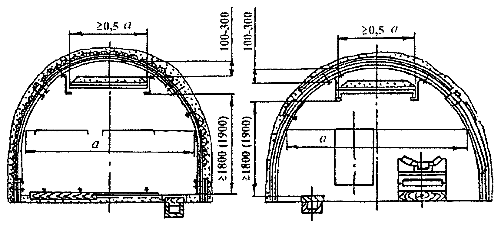
Figure 4 – Installation scheme shale zaslonіv at virobkah, zakrіplenih metalevim arched krіplennyam s spetsprofіlyu.
The distance between the shelves is taken as their width (600 ... 800 mm). Length shale barrier should be at least 20 m.
On each side of the shelf to be allowed to nail skirting height of 80 mm, which prevent the shedding of inert dust.
Shelves barrier should be easy to tip over from the air stream, but to be quite resistant to accidental bumps.
The effectiveness of shale barriers to a large extent depends on the quality of limestone dust. If inert dust caked or humidified, it should be replaced immediately.
Shale barriers are installed in dry places (without drip water), that is, in the workings to be rock dusting or whitewashing. [3]
3.8 Water barrier
Water barriers are arranged in a number of water–filled easily tipped or destroyed vessel capacity not exceeding 80 liters (typically 40 .. 50 hp) each, mounted on free-standing wooden shelves, located across the output from the roof (Pic. 5). Length water barrier should be at least 30 m.
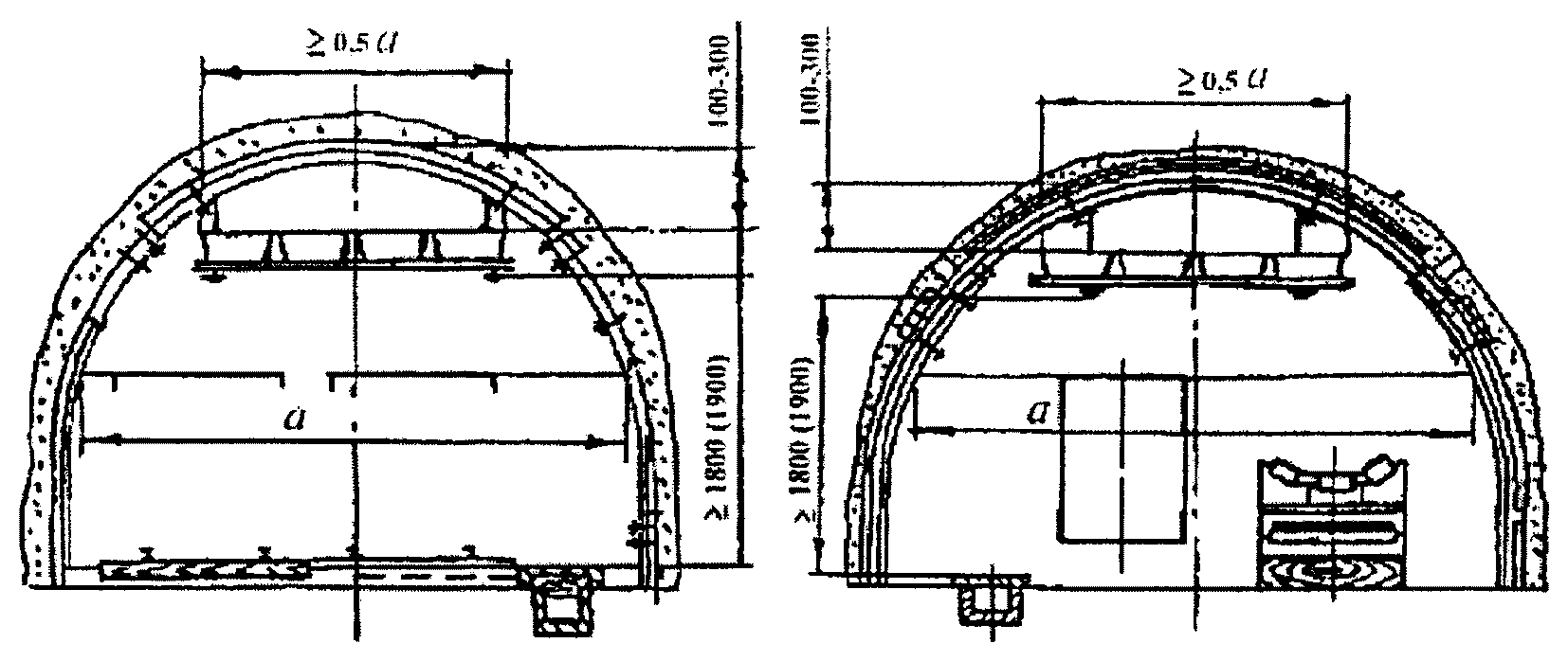
Figure 5 – Scheme of installation of the water in zaslonіv virobkah, zakrіplenih metalevim arched krіplennyam s spetsprofіlyu.
At the time, McNeil studies have been conducted to determine the effectiveness of vzryvogasyaschey water barriers and the establishment of the optimal parameters of their design. It was developed 11 designs of vessels that have been tested on the stand, as well as in experimental explosions in the metal tunnel and experienced mine. Bench tests have allowed to indirectly estimate the inertia of blood vessels and some of them are excluded from further testing. Containers used in the experiments, metal and wood, of high impact polystyrene, polypropylene and polyethylene, polystyrene and rezinoebonita. Analysis of the results of the research showed that the most effective are the vessels of plastic capacity of 40 ... 50 l. Therefore now to collision of water barriers are made of brittle plastic (polystyrene, polypropylene, polyvinyl chloride, etc.). Vascular parameters:
- Height 200 ... 260 mm.
- Width: the lower base — 150 ... 320 mm, the upper base — 300 ... 350 mm.
- Length: the bottom — 580 mm at the top — 640 mm.
- Weight — 2.6 kg.
Plastic Containers is more convenient to use than the vessels of other materials. Their term of office is usually more than 3 years. They do not corrode, are easy to transport and cost effective. Mass production of plastic receptacles for water barriers were spent at the Gorlovka repair–mechanical plant.
Trial check showed rather high efficiency of water barriers from the vessels equipped with freely lying and easily dumped plastic covers.
4. Measures for the prevention and containment of coal dust explosions
Due to the fact that the reservoir m3 related to dangerous exposure to coal dust, in the preparation of excavation site provides for the combined performance of dust explosion protection in accordance with Manual ...
. [4]
Washing of the water produced in the vent. roadway and Conv. 3 of the central roadway lava, as well as ventilation at the site. Walker 3 of the central lava at a distance of 200m from the lava. Rock dusting and washing of excavations carried out according to the schedule approved by the Chapter. engineer shaft. [1]
Rock dusting is made on the vent. The best–selling 3 of the central lava on the entire length, except 200m from the lava at the races.
For localization of coal dust explosions provides:
- Installation of shale barriers to Conv. 3 of the central drift of lava.
- Installation of shale barriers to vent. drift and ventilation. The best–selling 3 of the central lava.
Conclusion
Based on this work wecan make the following conclusions:
- Reduction of dust coming (junction formed dust in suspension).
- Comprehensive use of various methods to prevent, reduce dust, dust suppression.
- High-quality implementation of measures to combat the dust.
References
- Предотвращение выбросов угля и газа с помощью щелевой разгрузки / Николин В.И., Александров С.Н., Яйло В.В., Фридман Г.М. – Киев: Техника, 1990. – 98 с.
- Инструкция по безопасному ведению горных работ на пластах, опасных по внезапным выбросам угля, породы и газа.– МУП СССР.– М., 1989. – 191 с.
- Н.Р. Шевцов. Взрывозащита горных выработок (курс лекций): Учебное пособие для вузов. – 2-е изд., перераб. и доп. – Донецк : ДонНТУ, 2002. – 280 с.
- Л.Н. Карагодин, А.С. Кузмич, Н.А. Шальнов. Руководство по борьбе с пылью в угольных шахтах. – 2-е изд. перераб. и доп. – М., Недра, 1979 г. – 319 с.
- Смачивание пыли и контроль запыленности воздуха в шахтах / Р.Р. Кудряшов, Л.Д. Воронина, М.К. Шуринова и др. – М.: Наука. – 167 с.
- С.Н. Александров, Ю.Ф. Булгаков, С.Г Лунев, В.В. Яйло. Охрана труда в угольной промышленности (учебное пособие для студентов горных специальностей высших учебных заведений). Донецк: ДонНТУ, 2005. – 520 с.
- Кирин Б.Ф. Борьба с пылевыделением в шахтах / Б.Ф. Кирин, В.П. Журавлев, Л.И. Рыжих. – М.: Недра, 1983. – 199 с.
- Суханов В.В., Петулько С.Н./ Производственная пыль/. Медицина труда в угольной промышленности/: Сб. – Донецк: Изд-во ГП НИИ медико-экологических проблем Донбасса и угольной промышленности. 2000. – 21 c.
- Краснюк Е.П. Пылевые заболевания легких у рабочих промышленного производства Украины. Укр. пульмонол. журн. 1998. C. 13 – 16.