
Abstract
Сontent
- Introduction
- 1. Purposes and research problems
- 2. DC motor
- 2.1 How DC motor are arranged
- 2.2 Ways of excitation DC motor
- 2.3 Rotation frequency of DC motor:
- 2.4 DC motor breaking
- 3 Thyristor converter
- 3.1 Short informition
- 3.2 Schemes of rectification, principles of creation power chains in converters
- 4. DC drive DCS 800 which is used in laboratory stand
- 4.1 Advantages of DCS 800
- 4.2 Basic software
- 4.3 Electric drive system leader-follower
- 4.4 Communication board SDCS-COM-8
- 4.5 Functions of basic programming
- 5. 5710 board
- Conclusion
- References
Introduction
Now in practice of the adjustable electric drive the wide distribution was received by converters complete with the control system realized on the digital processor. But not always the HIGHER EDUCATION INSTITUTION can offer this equipment for training students to practical part. For anybody not a secret that the laboratory base of electrotechnical specialties of higher education institutions in Ukraine is morally obsolete, and today doesn't conform to high standards, and respectively and to high level laboratory students practice. Offered on the market laboratory equipment research
stands, aren't suitable for educational process, and application by it and it is rather in colleges and technical schools too. In this case the user is given rather limited opportunities at the choice of one of the standard control systems provided by developers, and to their setup. If it necessary to make more complicated control system for the purpose of improvement quality of regulation or expansion of its functionality there are the problems connected with realization of additional devices and their interface to the main processor. Interesting solutions are proposed by a number of the foreign firms connected with development of scalable hardware-software simulators based on PC, for example, power electronics devices and even complex electromechanical systems, working in the real time, operating systems of fast prototyping, etc. However the cost of the similar equipment is excessively high for universities [2].
Overcoming a problem of absence due to laboratory base consists in creation by young scientific hands individual
experimental installations focused on the solution tasks set for them. Quite often these tasks, encounters lack of experience of creation similar installations at researchers, and includes study project of the model, search and purchase suitable element base and the software, installation and adjusting, writing a program code, etc. that inevitably in this situation [5].
1. Purposes and research problems
Main objective of work is development and creation the laboratory stand for possibility of practical realization, management and supervision of various electromechanical systems with difficult parametrically and functionally uncertain objects [2].
2. DC motor
Direct current electric motors apply in those electric drives where the big range speed regulation, the big accuracy of speed maintenance o rotation of the drive, speed regulation up from nominal is required.
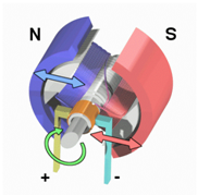
Figure 1.1 – Operation of the engine of a DC.
2.1 How DC motor are arranged
Work of an DC electric motor is based on the phenomenon of electromagnetic induction. From electrotechnics bases it is known that on the conductor with the current, placed in a magnetic field, force determined by the rule of the left hand works:
F = BIL, where I — the current proceeding on the conductor, B — induction of a magnetic field; L — conductor length.
When crossing by the conductor magnetic power lines of the machine, in it the electromotive force which in relation to current in the conductor is directed against it therefore it is called the return or counteracting (counter-EMF) is directed. Electric power in the motor will be transformed in mechanical and partially spent for conductor heating.
Structurally all electric DC motors consist the inductor and the aramature divided by an air gap. The inductor of DC motor serves for creation a motionless magnetic field of machine and consists main and additional poles. The frame serves for fastening of the main and additional poles and is an element of a magnetic chain of the car. On the main poles the windings of excitement intended for creation of a magnetic field in machine, on additional poles - the special winding serving for improvement conditions of switching are located. The armature consists of the magnetic system collected from single sheets, the working winding laid in slots, and a collector of the employee for a supply to a working winding dc current. The collector represents the cylinder got on a motor shaft and the elected from copper plates isolated from each other. On a collector there are ledges cockerels to which the ends of sections winding of an armature are soldered. Picking up current from a collector it is carried out by means of the brushes providing sliding contact with the collector. Brushes are fixed in brush holders which hold them in a certain situation and provide necessary pressing of a brush a collector surface. Brushes and brush holders are fixed on the traverse, connected with the electric motor case.
2.2 Ways of excitation DC motor
As excitation of electric motor understand creation in them magnetic field necessary for operation of the electric motor. Schemes of excitation of DC motors are shown on figure.
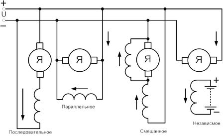
Figure 2 – Schemes of excitement of electric motors of a direct current: a - independent, b - parallel, c - consecutive, d - mixed.
On a way of excitement electric motors of a direct current divide into four groups:
1. With independent excitation at which a winding of excitation supply from a source with direct current.
2. With parallel excitation at which the excitation winding joins parallel to the power supply of a armature winding.
3. With series consecutive excitation at which the winding of excitation is included consistently with an armature winding.
4. Engines with the mixed excitation (compound) which have series and parallel of a winding excitation.
2.3 Rotation frequency of DC motor:
Frequency of rotation of the engine of a direct current:

where U — power line tension; Iя — anchor current; Rя — resistance цепн anchors; kc — the coefficient characterizing magnetic system; Ф — a magnetic flux of the electric motor.
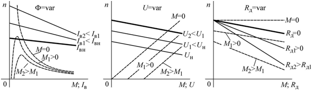
Figure 3 – Regulation of speed of DC motor
From a formula it is visible that the frequency of rotation can be regulated three ways: change of a excitation flux, change of voltage brought to the electric motor and change of resistance in an armature chain.
The broadest application was received by the first two ways of regulation, the third way is applied seldom: it is uneconomical, motor speed thus considerably depends on loading fluctuations. Mechanical characteristics which thus turn out, are shown in drawing [3].
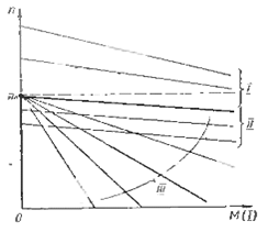
Figure 4 – Mechanical characteristics of the electric motor of a direct current at various ways of regulation of frequency of rotation
2.4 DC motor breaking
DC motor have three ways of braking: dynamic, recuperative and braking by opposed action [6].
- Dynamic braking is carried out by short circuit of a winding an armature via the resistor. DC motor starts working as the generator, transforming the mechanical energy reserved by it to the electric. This energy is emitted in the form of heat in resistance on which the armature winding is closed. Dynamic braking provides an exact stop of the electric motor.
- Recuperative braking is carried out in that case when the electric motor switched on in a network rotates the executive mechanism with a speed exceeding speed of ideal speed. Then EMF induced in an engine winding, will exceed value of voltage supply, current in a winding changes to the opposite. The electric motor passes to work in a generating mode, giving energy to a network. At the same time on its shaft there is a brake moment. Such mode can be received in drives of lifting mechanisms when lowering freight, and also at speed regulation of motorand during brake processes.
- Recuperative braking is the most economic way as in this case there is a return to an electric power network. In the electric drive of metal-cutting machines this way apply at speed regulation in systems of G– DC motor and EMD – DC motor.
- Braking by by opposed action is carried out by change voltage and current polarity in an armature winding. At interaction armature current with a magnetic field of a winding excitation the brake moment which decreases in process of reduction frequency rotation is created. At reduction of frequency rotation to zero electric motor has to be disconnected from a network.
3 Thyristor converter
3.1 Short informition
The thyristor converter of a direct current (TC) is the device which transformation alternating current in constant with regulation under the set law of output parameters (current and voltage). Thyristor converters intend for supply armature chains of motor and their windings excitement.
Thyristor converters consist following main knots:
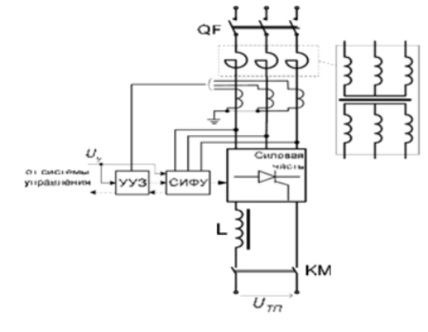
The transformer carries out coordination of entrance and output voltage of the converter and (as well as the current-limiting reactor) restriction current short, short circuits in entrance chains. Smoothing reactors intend for smoothing of pulsations straightened voltage and current. Reactors aren't provided if inductance of load is sufficient for restriction pulsations in the set limits.
Use of thyristor converters allows to realize practically the same characteristics of the electric drive, as when using rotating converters in systems the generator motor (G— M), i.e. to adjust over a wide range the frequency of rotation and the motor torque, to receive special mechanical characteristics and the necessary nature of course transients at start-up, braking, a reverse etc.
3.2 Schemes of rectification, principles of creation power chains in converters
Thyristor converters are carried out with single-phase and multiphase schemes of rectification. There are some settlement ratios of the main schemes rectification. One of such schemes is shown in fig. 5, and. Regulation of rectification voltage of Ua and current of Ia is made by change of angle control . In fig.5, a DB for an example nature of changing currents and voltage is shown in the three-phase zero scheme of rectification at active and inductive load [11].
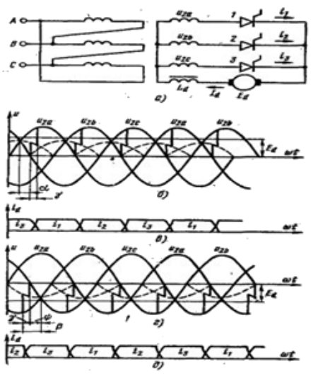
Figure 5 – The three-phase zero scheme (a) and charts of change of current and tension in vypryamitelny (b-c) and invertor (d-e) modes.
The angel shown on diagram gamma (switching corner), characterizes the period of time during which current proceeds at the same time on two thyristor. Dependence of average value rectification voltage Ua on a angle of regulation is called as the adjusting characteristic.
For zero schemes average rectification voltage is defined from expression [15].
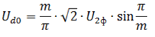
Where m — number of phases of a secondary winding transformer; U2ф – operating value of phase voltage of a secondary winding transformer.
For bridge schemes of Udo is twice higher as these schemes are equivalent to consecutive inclusion of two zero schemes.
In the three-phase zero scheme of a condition use transformer at usually applied connection groups of Y/Y and the triangle/star is worse because existence of a constant component a stream. It leads to increase in section of a magnetic conductor and, therefore, the settlement power of the transformer. To an exception a constant component of a stream apply connection secondary windings transformer in zigzag
that also increases settlement power a little. The increased level, pulsations of the rectification voltage together with the shortcoming noted above limits use of the three-phase zero scheme [17].
4. DC drive DCS 800 which is used in laboratory stand
4.1 Advantages of DCS 800
The drive meets the most rigid requirements of such systems as:
- Test benches, mine elevators, rolling mills, and also such installations without electric motors as;
- Electrolysis - Magnetic equipment – Charging units.
The built-in software allows to model all classical schemes: 12 – pulse scheme, systems of joint movement, two-engine schemes, control of a field reversal.
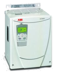
Figure 8 – Appearance of the complete ABB DCS 800 converter
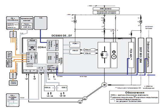
Figure 7 – Review of components of the converter
4.2 Basic software
The software of DCS 800 contains basic functions regulation of speed, flux current, armature current and voltage fn the motor. The flexible system of addressing teams allows to exercise control on consecutive fieldbus interfaces or system the leader - follower, or from external signals control units, and also on the mixed system [7].
The logical structure of the drive allows to configure the drive so that its actions were defined by the Profibus standard or corresponded to classical control methods [10].
Access to all parameters can be provided or by means of consecutive communication, or according to the IEC 61131, or standard on means of adaptive programming.
4.3 Electric drive system leader-follower
The drive is connected according to the scheme the Leader-follower. If the engines attached to the general shaft or the mechanism, rotate with an identical speed and with an identical torque.
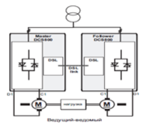
Figure 8 – Connection by the drive according to the scheme Leader-follow
4.4 Communication board SDCS-COM-8
DCS 800 contains the following interfaces for fast consecutive communication on an optical fiber:
- The DDCS protocol for communication with the AC800M controler
- Expansion of DDCS channels through AIMA-01 payment
- Communication of protocols in the scheme Leader-follower
- Communication from the personal computer (DriveWindow programs), system of remote diagnostics of NETA, and also CDP 312 from ACS800
4.5 Functions of basic programming
Figure 9 – Distribution of plugs by means of a macro.
(animation: 5 frames, 6 cycles, 433 kilobytes)
5. 5710 board
5710 represents ADC payment with high resolution on which devices of input-output of discrete signals also contain [12].
The analog part of a board allows to make measurements with a frequency of 70000 measurements a second. Initialization of the converter is carried out or under control board of the calculator (a processor payment) or by means of the 5710th counter/timer located on board. In the latter case measurements are made in a background mode. The counter/timer also can be used for performance of temporary measurements of general purpose or for PWM-signal generation.
To a board 5710 can be connected 16 unipolar or 8 differential analog signals. Resolution of ADC makes 12 categories about an entrance signal (-5. +5) V . Switching of channels is carried out in the program way. It is allowed to give on entrances signals voltage to (-15... + 15) V at absence on a supply board voltage. The amplifier located on a payment allows to change strengthening coefficient х1, х10, х100 by installation of crossing points. The entrance signal will make thus (+-5) V, (+-500) mV and (+-50) mV.
The board 5710 allows to carry out to 33000 measurements a second, and a board of 5710-1 - 70000 measurements in a second.
On a board also there are 2 analog outputs channel. The output signal also is set by crossing points and can be (0. 5) V, (+-10) V or (+-5) V.
The board 5710 allows to work with 19 discrete lines of input-output. Lines are grouped in 3 groups. One group of three lines can work only for an exit, the following group of 8 lines can be configured by two subgroups on 4 lines on an entrance or on an exit, and the third group of 8 lines also can be configured on an entrance or on an exit, but all group entirely.
On a board are also available to the programmer of three 16 digit counters/timers. The first counter/timer is a divider for an entrance signal with a frequency of 4 MHz. The coefficient division can be set programmatically. The second counter/timer is used as a divider of the frequency arriving from the first counter/timer and forms a periodic signal start of the analog-digital converter. Thus the period of poll can be from 40000 measurements a second to 3 measurements in hour. The last counter can be used as the counter/timer of general purpose, thus its input and output lines are brought to the socket of discrete port, and the entrance can be connected to the internal generator of 4 MHz by means of crossing points.
Conclusion
Universal experimental installation with possibility of practical realization, control and supervision of various electromechanical systems is created. The simulation in installation realized by the mechanism
imitations of various technological processes. Algorithms of DC drive control are realized, pilot researches of operation in electric drive are conducted. Feature of installation is possibility realization of algorithms control practically any complexity and is exclusive at program level that is important and in educational process. It opens ample opportunities at modernization of operating electric drives by reprogramming. Installation is already used as the range for approbation of new algorithms of control when training graduate students and masters, and also when carrying out practical and laboratory works on disciplines Complete electric drives
[14].
Final end: December, 2014. The full text of work and materials on a subject can be received at the author or his head after the specified date. This part of the paper the exclusively survey. Further work will be directed on a pilot study and completion of available results in the sphere of digital control systems [13].
References
- Чермалых В. М. Идентификация параметров физической и виртуальной моделей частотно-регулируемого асинхронного электропривода / Национальный технический университет Украины
КПИ
, г. Киев / Проблеми енергоресурсозбереження в електротехнічних системах. Наука, освіта і практика № 1/2011 (1) с. 54-55 - Полилов Е.В. Исследовательский стенд дляя апробации алгоритмов управления сложными электрическими системпми. / Украина Алчевск с. 481-487
- Передерий А.В. Імітація навантаження електроприводу поздовжньо-стругального верстату / Наукові праці Донецького національного технічного університету с. 133-137
- Толочко О.И. К вопросу об изменении типовых структур цифровых систем управления комплектными электроприводами / Наукові праці Донецького національного технічного університету с. 188-193
- Прітченко О.В. Концепция построения малогабаритных лабораторных стендов / Кременчуцький державний університет імені Михайла Остроградського / Електромеханічні і енергозберігаючі системи. Випуск 2/2010 (10).
- Гладырь А.И. Лабораторный комплекс для иследования процесса трогания производственных механизмов / Кременчугский государственный политехнический университет имени Михаила Остроградского.
- Голдсуорт Б. Проектирование цифровых логических устройств / Б. Голдсуорт. – М.: Машиностроение, 1985. – 288 с.
- Шинкаренко В. Ф. Лабораторный комплекс для исследования статических и динамических харакетристик асинхронных машин / Електромеханічні і енергозберігаючі системи. Випуск 2/2012 (18) с. 113-115
- Орловський І. А. Модернизация лабораторного стенда подвесного конвейера Part_2-8 / Електромеханічні і енергозберігаючі системи. Випуск 2/2013 (22). Частина 2 с. 427-431
- Орловський І. А. Модернизация оборудованием фирмы VIPA лабораторного стенда с манипулятором М10П / Електромеханічні і енергозберігаючі системи. Випуск 3/2012 (19) с. 597-599
- Полилов Е.В. Практическая реализация и исследование релейно-робастных алгоритмов управления синхронными электродвигателями Сборник ХПИ 2010-3 / Теоретические вопросы 98 автоматизированного электропривода с. 90-98
- Заквасов В.В. Программно-аппаратный комплекс для исследования встроенных систем управления / Електромеханічні і енергозберігаючі системи. Випуск 1/2010 (9)
- Кореньков Э. В. Регулирование технологических параметров гидротанспортных систем с использованием исследовательского комплекса-тренажёра / Електромеханічні і енергозберігаючі системи. Випуск 2/2013 (22) с. 117-125
- Бондаренко В.І. Современные подходы и методы изложения прикладных дисциплин при подготовке специалистов по электромеханике Сборник ХПИ 2010-21 / Учебный процесс. Дискуссии с. 558-559
- Петров Д. СТА Применение в учебном процессе современных средств разработки СРВ
- Ефимов И.Г. Стенд для исследований частотно-регулируемых электроприводов / 5 международная конференция по автоматизированому электроприводу АЭП-2007 Санкт-Петербург, 18-21 сентябрь 2007 с. 216-218
- Сердюк А. А. Экспериментальный комплекс гидротранспортной установки для исследования кавитационных систем / Проблеми енергоресурсозбереження в електротехнічних системах. Наука, освіта і практика № 1/2011 (1)