
Abstract
Maintenance
- Introduction
- 1. Features of construction of digital motor control
- 2. Recording device signals based on hardware computing platform Arduino
- 2.1. Urgency of the problem
- 2.2. Goals and objectives of the study
- 2.3. The hardware part
- 2.4. The software part
- 3. Development of an experimental stand for research digital engine control systems DC-based high-speed PC-compatible expansion card 5710
- 3.1. The structure of the stand
- 3.2. Overview of thyristor converters series BTU
- 3.3. DC motors
- 3.4. The control part
- 3.5. The software part
- 3.6. Model system for automatic control of the DC motors
- Conclusion
- References
Introduction
In motor control systems are two main ways of processing information: analog and digital. At this point digital signal processing almost completely supplanted analog. Progress in this part of the achievements in microelectronics allow to create computational tools that have high performance, small size, weight and power consumption. Interest in digital signal processing due to the fact that it is based on the device, you can create with performance unattainable with analog methods. Furthermore, the use of digital processing devices in some cases, it is more advantageous from a technical and economic point of view because of their versatility and ability to work in various modes.
Aim of this work is the development of digital media and the formation of the setpoint signal processing applied power management systems. The work consists of two stages:
- Development recording device signals based on hardware computing platform Arduino
- Create experimental stand for exploring digital systems DC motor control based on high speed PC compatible expansion board ADC/DAC 5710 Octagon systems.
1. Features of construction of digital motor control
To the digital control systems (DCS) are systems consisting of digital elements. The term digital item
(CE) means some
constructive electrical unit discrete action that performs various functions – logical, computational, converting, storing signals.
As part of the DCS digital elements form the nodes to perform certain management tasks. Fig. 1 is a diagram of a DCS coordinate x
actuator where ЦЗУ – digital setting device, ЦС – digital adder, ЦР – digital controller, ЦАП – DAC, АЦП – analog-to-digital converter,
УП-Д – System Managed inverter-motor, which is the output УП executive SUEP part.
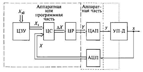
Figure 1 – Diagram of the digital control system electric drive
This scheme DCS similar in structure to the continuous SUEP with the same functional units, except for the DAC and ADC, but satisfied analog elements.
Pros DCS determined advantages of digital elements compared to analog – big noise immunity and precision sensor position and velocity, simplicity and ease of digital programs on job movement actuator and undeviating a tendency to reduce the size and cost of the CE to improve the reliability and level of integration of digital nodes.
Functional units DCS shown in Fig. 1 may be implemented in two ways:
- Hardware – each functional unit is an independent separate unit consisting of DCS made on chips small and medium-scale integration;
- Software – functional units run on a computer or microcontroller, and their functioning is determined by an algorithm program of the device.
To change DCS control algorithm for hardware method requires replacement and relevant control units. A soft method for changing the control algorithm requires only a change in the program on the same hardware components. These are widely used in the DCS application in electric plants, where possible changes in technological processes, therefore, requires changes in top-level management tasks. Due to the rapid development of advanced manufacturing technology of microprocessor devices improve the quality and reduce the cost of software is deeply rooted in the way the control system actuators [1].
2. Recording device signals based on hardware computing platform Arduino
2.1. Urgency of the problem
When designing systems for automatic control of electric often need computer processing of analog the signals of the speed sensors, current, voltage, position, that is to receive the numerical signal values by using analog-to-digital converter (ADC). Subsequently, digital signals may be used to provide feedback to control system, or to graphically display the status of the adjustment. Development of an inexpensive device registration signals that can be used in educational and scientific and research work, is still a big relevance.
2.2. Goals and objectives of the study
The purpose of this phase of the work is to develop and provide a device registering low frequency analog signals in the form of voltage varying voltage range ± 10V. Such a device is useful as a digital oscilloscope to sensor signal voltage, current, tachogenerators.
2.3. The hardware part
To solve the problem was used the ADC board, implemented on a platform Arduino [2], which is currently is very popular thanks to the convenience and ease of programming language, open architecture and software code. There are several versions of the platform Arduino, characterized mainly by the type of microcontroller family ATmega. Principle can be used either platform versions, and, strictly speaking, not all features of the platform will be at this used. In addition to recording signals with the Arduino can also organize and generating control signals outputs from the supporting PWM. In addition, it is possible a software implementation of digital filters, regulators or any degree
Below is the description of the developed 4-channel digital video recorder based on the platform Arduino Mega (Fig. 2) using microcontroller ATmega2560. To work, you must connect Arduino Mega board to the USB port of a personal computer.
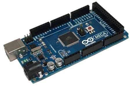
Figure 2 - Board ArduinoMega
Arduino analog inputs are rated from 0 to 5 V, so the input signals must be pre-normalized, for which there is a separate charge. On-board signal conditioning inverting amplifier circuit implemented on the basis of operating amplifiers (op amp) with an offset signal is level. OS used for power bipolar power supply ± 12,5 V (based on 2 unipolar sources).
Fig. 3 shows the appearance of the developed device. For simultaneous normalization four signals used chip TL074CN, which combines four Shelter.
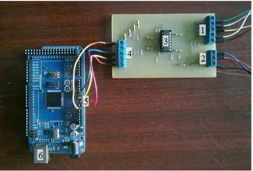
Figure 3 – General view of the recording device based on Arduino Mega: 1 – input terminals normalizing board (4 inputs and GND); 2 – supply terminals (12.5 V, 12.5 V and GND); 3 – chip TL074CN; 4 – output terminals normalizing board (4 outputs and GND); 5 – analog inputs Arduino (A0, A1, A2, A3 and GND); 6 – USB-port for connecting to a computer.
The principle of operation of the device registration shows the following scheme:
Figure 4 – The principle of recording devices (animation: 8 frames, 547 KB)
2.4. The software part
The software part of the project is implemented in the Arduino IDE [3] and Processing. The program is responsible for receiving numerical data computer development environment written in Arduino IDE – application in Java, which includes a code editor, compiler, and a transmission unit firmware in charge.
Visualization program written in an open programming language Processing [4], based on Java; program listing here omitted.
Fig. 5 shows an example of registration of three signals (voltage ramp, speed and armature current DC motor) with the developed device.
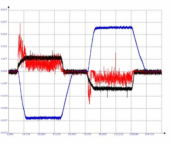
Figure 5 – Window registration program
3. Development of an experimental stand for research digital engine control systems DC-based high-speed PC-compatible expansion card 5710
3.1. The structure of the stand
Power part of the stand consists of two DC motors series PBST-32 with integrated tacho, two reversible BTU series thyristor converters and relay-contactor control system.
Control part is the instrumentation panel, personal computer with built-in high-speed board expansion ADC/DAC 5710 Octagon systems, as well as input and output galvanic isolation.
Schematic diagram of the stand is shown in Figure 6.
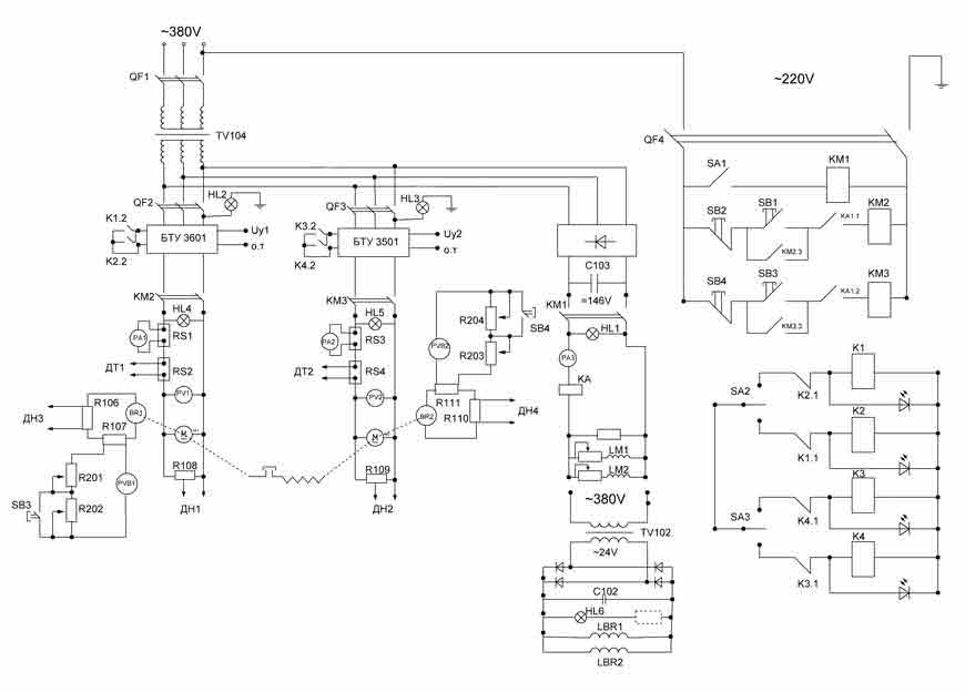
Figure 6 – Schematic diagram of the stand
3.2. Overview of thyristor converters series BTU
In this paper reversible thyristor converters used BTU-3501 and BTU-3601. Their devices are similar, so we consider structure of one of them – BTU-3601.
Thyristor converter BTU-3601 is designed to regulate the speed as conventional DC motors with independent excitation, high-torque motors and.
Power circuit of a (Fig. 7) consists of two sets of three-phase bridge thyristor working on the principle of separation management. Connect the inverter to the power grid is made through a matching transformer. Reverse the rectified voltage achieved by antiparallel connection of two sets of three-phase thyristor bridge. When you work one set of device logic forbids to pulse control to another. The specifics of the three-phase bridge rectifier circuit controlled in discontinuous is the need to create two pulses for thyristor control.
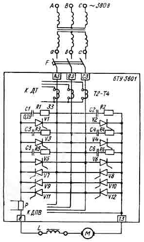
Figure 7 – Schematic diagram of the power of the BTU-3601
Functional diagram of the BTU-3601 is shown in Figure 7.
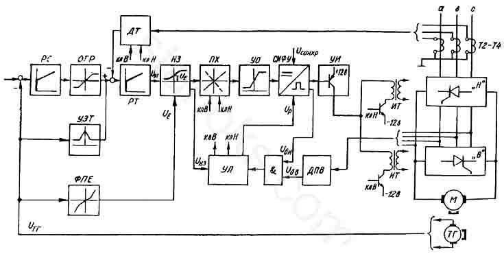
Figure 8 – Functional diagram BTU-3601
Inverter control part (Fig. 8) contains a set of analog controllers, as well as current and speed sensors, but in this paper they are not used as the control signal is fed directly to the non-linear element (NC). NC transfer coefficient has a dependence inverse coefficient transfer thyristor converter in the discontinuous current zone.
Of bipolar control voltage non-linear element is converted switch characteristics (HRP) in unipolar. Thus, in static mode, the drive to the control authority Sifu (UO) is served only negative polarity voltage, regardless of operating a set of thyristors.
SIFU governing body provides the minimum and maximum limit angles regulation setting the initial angle regulation.
Sifu generates control pulses for the thyristors. Phase shift with respect to the pulse power voltage thyristor proportional to the voltage applied to the sifu from UO.
Pulse amplifiers (IAs) negotiate power output pulse transformer with Seth. In addition, twinning occurs at UI pulses.
Separate control logic unit (UL) is used to generate signals kl.V kl.N and managing keys B and H in the sensor current switch circuit characteristics and pulse transformers. Command for switching STR kits is changing polarity of the signal at the output of NC.
Lack of control current through the thyristor valves made conductivity sensor (DPA).
Elements and performs the logical multiplication of blocking signals and the output is a logic signal at the unit level period of time when there is no current through the thyristor and thyristor control pulse.
When switching command sets and available at the output of the AND unit-level signal, generates a signal STR zero level, which starts counting the time delay element. For the period of delay pulse transformers both sets are disabled, and pulse shaping control Sifu prohibited. After time delay there is a connection to the specified pulse transformer kit, and also allowed the formation of pulses in sifu [5].
3.3. DC motors
DC motor is widely used in various fields of human activity, ranging from the use of traction drive used in trams and trolleybuses, ending the drive rolling mills and hoists, which require maintenance drive speed with high accuracy, as well as the regulation up to par performance.
The main positive features that distinguish the DPT of the induction motor:
- Flexible starting and control characteristics
- Two-zone regulation, which allows to reach a rotational speed of 3000 rev/min.
Negative traits:
- Complexity and high cost of manufacture
- In the process, need constant supervision, as the collector current collector and brushes have a life of its own that subsequently leads to a constant maintenance of this type of engine.
DC motor is used only in cases where the use of an AC motor is impossible or extremely impractical.
The DC motor comprises an inductor (stator) and the armature (rotor), separated by an air gap and collector current collecting brushes, as well as structural elements of the engine (Fig. 9).
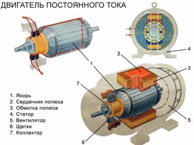
Figure 9 – The design of the DC motor
Inductor is a base frame, basic and additional poles that combine to create the magnetic field of the motor. Stand serves that would fix the main and additional poles of the magnetic system of the engine. Poles are located on the main winding, and additional – special windings, which serve to improve commutation.
Anchor consists of individual sheets in the windings arranged in the grooves and have a collector which serves to supply DC a working coil.
Collector has a cylinder which consists of plates insulated from each other, is fitted on the motor shaft. Brushes are used to pickup current collector, which are enshrined in the brush holders providing the correct position and press on the surface of the collector.
DC motors are classified according to the stator magnetic system:
- DC motor with permanent magnets;
- DC motor with electromagnets:
- DC motor with independent excitation
- DC motor series excitation
- DC motor shunt
- DC motor mixed excitation
Wiring diagrams of the DC motor is shown in Figure 10.
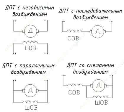
Figure 10 – Wiring diagram of the DC motor
Various connection schemes stator windings significantly affect the electrical characteristics of the drive and traction [6].
A forthcoming standused DC motors with separate excitation series PBST-32 capacity of 1.2 kW, which designed to work with drives shirokoreguliruemyh control range up to 1:2000 (for the machine tool). Engines PBST – reversible and performed with integrated tachometer.
3.4. The control part
Basis of the digital control system is a high-speed stand expansion board ADC/DAC 5710 Octagon systems (Fig. 11).
5710 is a card with a high resolution ADC, which also contains an input/output of digital signals.
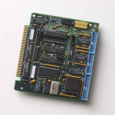
Figure 11 – Board 5710
Analog part of the board allows for measurement at a frequency of 70,000 samples per second. Initialization converter carried out or running board computer (CPU board) or by on the adapter 5710 counter/timers. In the latter case, measurements are performed in the background. The counter/timer can also be used to perform temporal measurement utility or to generate a PWM signal.
By 5710 board can be connected 16 unipolar or 8 differential analog signals. The resolution of the ADC is 12 bits of the input signal (-5 ... +5) B. Changing channels under software control. Allowed to apply for inputs voltage signals to (-15...15) In the absence of on-board power supply. An on-board amplifier allows you to change gain x1, x10, x100 by setting jumpers. The input signal in this case will be (+-5) B, (+-500 ) mV and (+ -50 ) mV respectively.
Board 5710 allows up to 33,000 measurements per second, and the fee 5710-1 – 70,000 measurements per second.
The board also has two analog output channels. The output signal is also given, and the webs may be (0...5), (+-10) V or (+-5) B.
Board 5710 lets you work with 19 discrete I/O lines. The lines are arranged in three groups. One group of three lines can work only on output, the next group of 8 lines can be configured in two subgroups to 4 lines on input or output, and a third group of lines 8 can be configured as input or output, but throughout the entire band [7].
In this paper are utilized 7 analog inputs and 2 analog output board 5710. Inputs are signals from sensors speed, current and voltage outputs - reference signals for each engine.
To isolate the control part of the power in the stand provided galvanic isolation voltages ADAM-3014, SCM5B41 and currents SCM5B40. Input voltage junctions -10...+10 V current interchanges -100...+100 mV output -5...+5 V [8].
3.5. The software part
Programming the control system consists of the following stages:
- Work in Windows:
- Obligatory deleting old files and model visualization
- Creating a model of a control package Matlab/Simulink and its compilation command Tools> Real-Time Workshop> Build Model. At this time, new files and model visualization in the folder ...\matlab\work
- Work in QNX
- Running QNX with the task sampling frequency (in this paper we use a sampling rate of 0.5 ms)
- Launch the file manager and team #mqc replacing old models and visualization files to new folders and 1/system/bin 1/system/config respectively
- Exit from the File Manager and launch a graphical editor Photon team #ph
- Running the model in the QNX team #system/bin/motor109
- Running the program visualization QNX team #system/bin/main
Result of these actions is the ability to control the drive of the computer and display graphs of origin the system screen.
Advantage of this control method is ease of use, because it is possible to change the parameters of the model in real time. Thus can be quickly setting regulators, modify smooth acceleration and deceleration of the engine, the value of and control the reference signal necessary coordinates (speed, current, voltage) in real time.
Disadvantage of such a system, in my opinion, is the need to move from one operating system to another when editing model.
Figure 12 shows the appearance of the model in the package Matlab/Simulink.
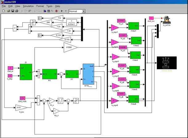
Figure 12 – Appearance model in Simulink
The model can be divided into the following parts:
- Management system (closed-loop or open-loop, represented only RFG). This part of the model can be edited by the operator. The important point is the possibility of linking the model parameters visualization program by prescribing the right values in the file main.cfg, allowing then modify them in QNX. This greatly facilitates the configuration of the system management, as it allows real-time change the parameters of regulators.
- Subsystem Model 5710 board. This block specifies the parameters necessary for communication with the computer hardware in particular, it is possible to specify the number of defining impacts, feedbacks and signals to be registered in the program visualization.
- As means of digital signal processing in this model provides the first -order digital filters, whereby you can get more kachetvennye nezashumlennye signals from the sensors, which is very important when setting up a closed loop control. Filter time constant can also change the software in real time.
- Outputs are model file recording and visualization.
Exterior visualization programs in QNX is shown in Fig. 13. It built graphics speed, current, and voltage reference signal to anchored by soft start and braking Engine.
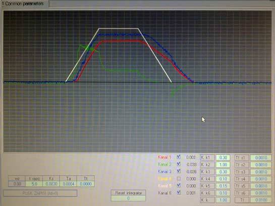
Figure 13 – Window visualization programs in QNX
3.6. Model system for automatic control of the DC motor
As the main model is the dual speed control system of the slave DPT, the block diagram which is shown in Figure 14.
Current regulator choose PI type and speed controller – P-type. The transfer functions of the current regulator and speed according to the setting to have optimum modular [9] form:
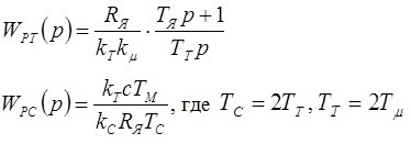
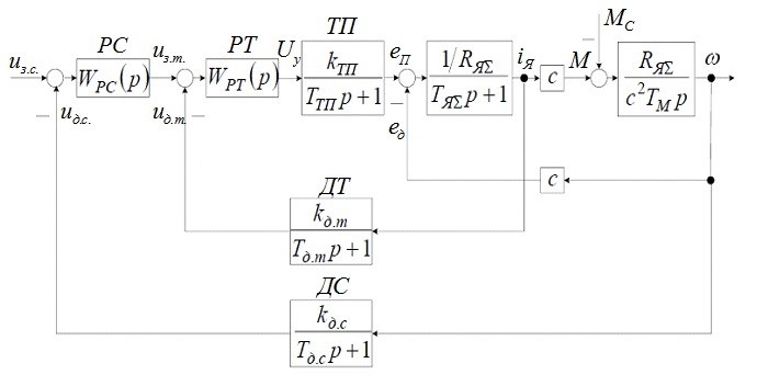
Figure 14 – Block diagram of a two-slave control system DC motor
Conclusion
This master thesis is devoted to the development and research of formation means defining impacts and signal processing the drive.
First phase of work at the time of writing the abstract completed. Its result is the establishment of an effective device for recording sensors in the range -10...+10 V on the basis of the computing hardware platform Arduino. The resulting device can be used as a four-channel digital oscilloscope for investigation of low-frequency signals in a bandwidth of 1 kHz.
Second stage is the development of an experimental stand for the study of digital motor control on the moment is not complete. My future work will be in the pilot study and revision of existing results.
This part of the paper the exclusively survey. Further work will be directed on a pilot study and completion of available results in the sphere of digital control systems.
References
- Терехов В. М., Осипов О. И. Системы управления электроприводов. – М.: Академия, 2005. – 300 с.
- Официальный русскоязычный сайт платформы Arduino [electronic resource] – Аccess mode: http://arduino.ru/
- Официальный сайт среды разработки Arduino IDE [electronic resource] – Аccess mode: http://www.arduino.cc/
- Официальный сайт среды разработки Processing [electronic resource] – Аccess mode: http://www.processing.org/
- Привод БТУ 3601. Подробное описание принципов работы. – 111 с.
- Двигатель постоянного тока. Схемы соединения и характеристики ДПТ [electronic resource] – Аccess mode: http://h4e.ru/elektricheskie-mashini/133-dpt-shemi-harakteristiki
- Плата 5710 Octagon System. Руководство пользователя [electronic resource] – Аccess mode: http://www.octagonsystems.com/
- Оффициальный сайт компании Dataforth [electronic resource] – Аccess mode: http://www.prosoft.ru/products/brands/dataforth/
- Чекавский Г.С. Конспект лекций по СУЭП, ДонНТУ, каф. ЭАПУ, 2012 г.
- Официальный русскоязычный сайт платформы Arduino [electronic resource] – Аccess mode: http://arduino.ru/