
Abstract
Contents
- Introduction
- 1. Relevance of the topic
- 2. Research goals and objectives, expected results
- 3. Key issues that must be addressed in this paper
- 4. An overview of the frequency control methods
- 4.1 Scalar system frequency control
- 4.2 Vector control system
- 4.3 Direct torque control
- Conclusion
- References
Introduction
Mine lifting installation is a complex mechanical system consisting of the following elements: the vessels, the winding, gears, motors, pulleys connected by elastic elements: ropes, shafting, clutch springs. They provide the issuance of mineral, as well as the movement of people and goods. Therefore, the reliability and performance of the elevator installation is a very important characteristic.
Figure 1 – Ascent and descent of the skip in the shaft.
(animation: 8 frames, 5 cycles, 184 kilobytes)
Asynchronous squirrel-cage motor provides high reliability in its operation, as well as the most economical energy consumption. However, there is a significant disadvantage — poor regulation properties. Therefore, previously applied to the drive mechanisms of unregulated or regulated within a small range. Currently developed and continue to develop new management systems (vector control, frequency–current control, direct torque control), allowing most to approximate inductive machine (IM) by adjusting its properties to the DC motor, extend the scope of its application [5].
Due to the sharp rise in the cost of electricity efficiency of the system DC decreased significantly, so far, the trend is the shift to energy-efficient AC system, including the need to note the frequency converter-induction motor (FC-IM).
Application of FC IM reduces the cost of the equipment, to form the desired tachogram movement and provide the system with a high energy performance. As the drive converters can be used with direct connection, or with DC link [2].
1.Relevance of the topic
The relevance of this work is due primarily to the fact that the AC motor control has improved significantly over the past two decades. It has become a trend due to new management techniques and ideas put forward by researchers from around the world which means that soon finds its application in mining and other industries.
2. Research goals and objectives, expected results
The aim of this work is to study the transient processes occurring in the system, using different frequency regulation laws. The analysis will be carried out with the help of mathematical modeling in the software package MATLAB.
3. Key issues that must be addressed in this paper
- Simulation of transients in the system at various laws and regulation, taking into account various factors such as the change in mass due to the hoisting rope winding, changing the radius of the drum
- Create laboratory bench to validate data obtained by modeling
- Further research and improvements
- The data analysis and conclusion
4. An overview of the frequency control methods
4.1 Scalar system frequency control
Asynchronous ED with scalar frequency control is used to mechanisms of medium and low power, which do not require deep speed control (often limited range of adjustment is 10:1), and high quality transients [1].
Frequency control is to provide the desired static characteristics of ED by performing a certain ratio between the amplitude and frequency of the voltage that is applied to the stator AD. Functional diagram of the system shown in Figure 2
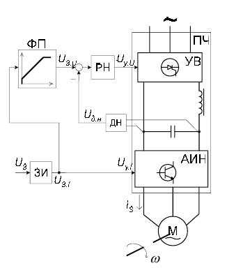
Figure 2 - Functional diagram of the system of scalar frequency control
Mechanisms controled by frequency scalar control systems usually do not require high accuracy and quality of transients. At the same time, such a system even without using speed feedback , allow to obtain a rigid mechanical characteristics same as in DC drive . Besides stiffness characteristics , an essential requirement of the scalar control system is to to provide surge capacity for maximum (critical) torque not less than a predetermined level.
In view of the ease of implementation of the principle of scalar control open and closed system "FC - IM" with scalar control are very widespread. To provide the required stiffness characteristics and overload capability in function converter FC implement certain relationship between the frequency reference voltages
and a refference voltage amplitude
corresponding to the so–called law of frequency control. This dependence can be linear or nonlinear.
Control law provides the required characteristics in the first zone (down from the nominal frequency), and if necessary regulate speed above nominal . Point corresponding to the boundary of speed control on the characteristics of FC, called field weakening point.
Speed control range in open–loop system is typically less than 10:1 (at constant load). Limitation of current and torque at start IM achieved in open-loop control with ramp [6].
The main drawback of the scalar frequency control systems is the difficulty in the implementation of quality control in transient dynamic modes, including restrictions coordinate ED (voltages, currents, moments) for possible overloads by the mechanism or deviations mains voltage. The reason for this is the complexity of electromagnetic processes occurring in IM.
4.2 Vector control system
Vector control, in contrast to the scalar implies provision of the law of frequency control, not only in stable but also in transient operating [3]. This ensures high quality performance as in statics and dynamics. In vector control torque and speed of IM most widely used control law
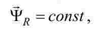
comprising continuous current stabilizing both the module and the angular position of the rotor flux vector. The law allows you to get the best static characteristics, and at the same time characterized by the implementation of a simple algorithm.
To implement the control law control system constructed in coordinate system, traditionally denoted by d, q, oriented along the vector of the rotor flux linkage when the real d-axis coordinate system strictly aligned with the rotor flux linkage vector .
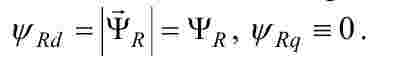
Functional diagram is shown in Fig. 3. The power part consists of FC based on voltage inverter with PWM and IM.
The system provides a direct measurement of the phase currents stator in two phases and speed.
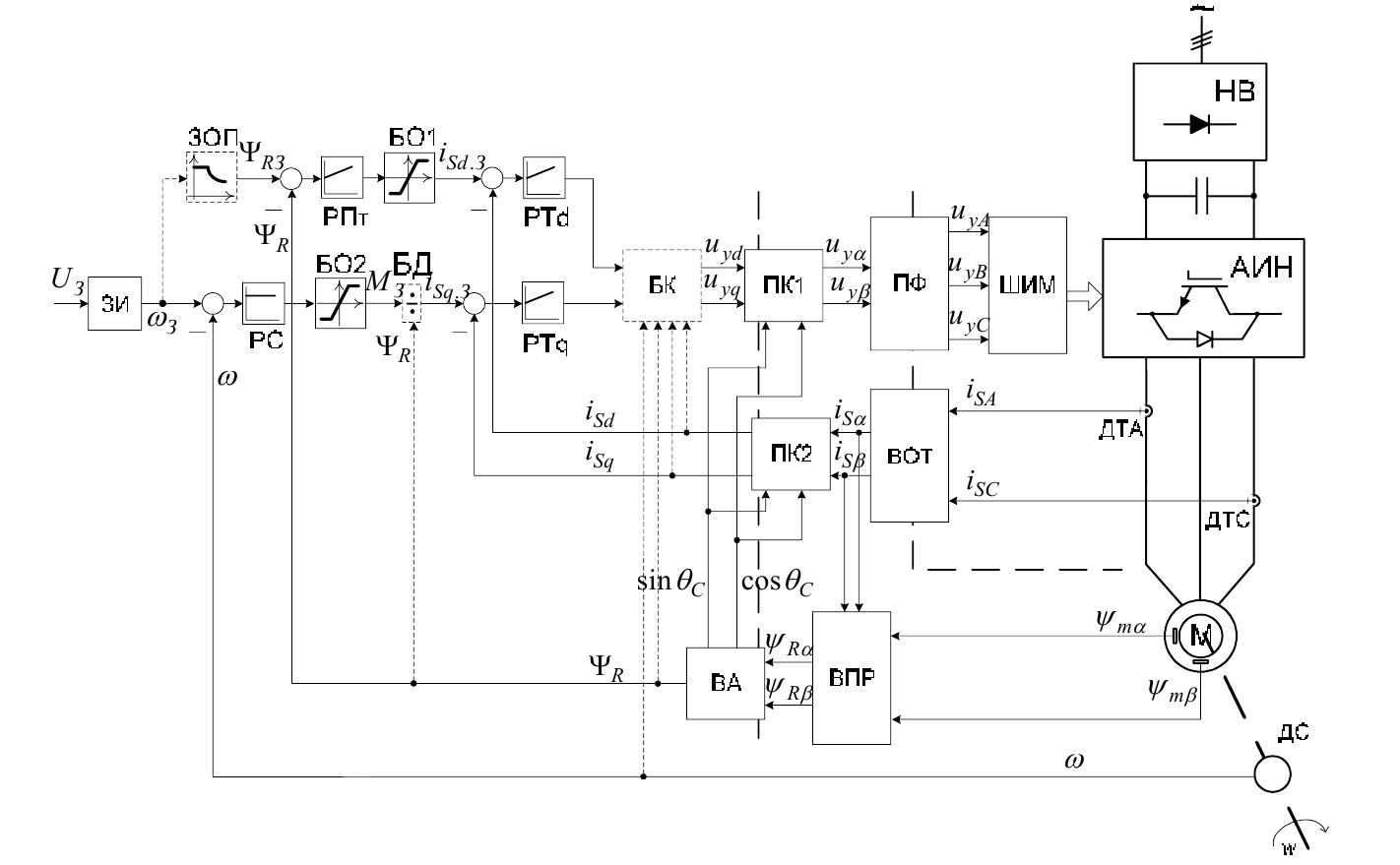
Figure 3 - Functional diagram of vector control system
The main disadvantages of the system is considered to be:
- he complexity of the regulatory system and the awkwardness of calculations related to the need to coordinate system orientation. Therefore, at present the implementation of systems of vector control is performed only by means of microprocessor technology [7]. Developed in the 1970s–1980s. device analog implementation of vector control systems are not widely used in industry because of errors introduced by regulation and drift parameters of the elements.
- Inefficiency measurements the rotor flux linkage using Hall sensors (or more measuring windings) because of their low reliability. At the moment, instead of directly measuring the flow use its indirect determination using mathematical models stream or observers that are based on the mathematical connection with the vector flux vectors of electrical quantities, and the speed easily accessible for measurement.
4.3 Direct torque control
Direct torque control (DTC - Direct Torque Control) is a development approach to the construction of the vector control systems IM. First industrial designs systems DTC, developed by ABB, appeared in the mid–1990s. DTC task is to ensure a rapid response electromagnetic torque to the control IM. Unlike vector control where torque control is performed through the stator current control, a system with DTC control the stator flux [4]. Functional diagram is shown in Fig. 4
Management principle: if kept constant module stator flux, the electromagnetic torque can be changed as quickly as possible to quickly change the angle theta. Both of these tasks can be accomplished by exposing the generalized vector of the stator voltage.
Figure 4 - Functional diagram of the system of direct management
- The advantages of the DTC system are:
- ease of implementation, the hardware is one and universal for different types of induction motors;
- high speed - the time of processing the torque reference from 1.0 ... 1.5 ms;
- low sensitivity to changes in IM parameters. At the same time, the drawbacks of DTC are:
- relatively large fluctuations of the moment, which is reduced due to torque accuracy;
- worse current shape compared to the vector control systems;
- the volatility of the switching frequency, which generally depends on the frequency, as well as torque setpoint.
- Improvement of inverter keys selection algorithm;
- Using "partial use vector" for the interval of discreteness ("duty cycle");
- Using advanced PWM, which is based in Estimates in advance for a period of time the extent of deterioration of quality system, and the formation of the stator voltage vector, taking into account the need to adjust these parameters.
Conclusions
The paper describes the main methods of frequency control of IM with squirell cage IM, as well as highlighting their strengths and weaknesses. You may notice that the system are not only for the quality that they can provide, but also the complexity of implementation.
The purpose of this paper is to present an unbiased comparison of methods of regulation to allow users to choose a more suitable solution for any task that requires quality control speed.
Since this work at the time the site is still in progress, it is difficult to draw any conclusions as will compare the results obtained by numerical simulation results obtained in practice. We can only say that the introduction of IM squirrel cage is an important task, which later will not only increase productivity but also to make the drive more economical, that due to the rising cost of electricity is a challenge.
References
- Чекавский Г.С. Конспект лекция по СУЭП, ДонНТУ, каф. ЭАПУ, 2012 г.
- Усольцев А.А. Общая электротехника // Учебное пособие. СПб.: СПбГУ ИТМО, 2009. - 301 с.
- Виноградов А.Б. Векторное управление электроприводами переменного тока / ГОУВПО «Ивановский государственный энергетический университет имени В.И. Ленина». – Иваново, 2008. – 298 с.
- Шавелкин А.А. Энергосберегающий высоковольтный преобразователь частоты с прямым управлением асинхронным двигателем / Шавелкин А.А., Сажин В.А., Прокопенко И.В. // Науково-практична конференція "Донбас 2020: наука і техніка - виробництву", 5-6 лютого 2002 р., Донецьк.
- Чиликин М.Г., Сандлер А.С. Общий курс электропривода. - М.: Энергоиздат, 1981. - 576 с.
- Толочко О.И., Чекавский Г.С. Моделирование систем электропривода переменного тока. Лабораторный практикум [электронный ресурс] – Режим доступа: http://www.twirpx.com/file/71461/
- Matlab R2013a documentation center [электронный ресурс] – Режим доступа: http://www.mathworks.com/help/documentation-center.html