
Abstract
- Introduction
- 1. Relevance, condition, purpose and objectives
- 2. Analysis systems move the tunnel boring machine
- 2.1. Analysis of system design movement boring machine
- 2.2. Structural diagram of moving the tunnel boring machine
- 2.3. Select a block of the executive body
- 3. Improving the efficiency of
- 3.1. Analysis of structural schemes mining thin bed
- Conclusions
- List of sources
Introduction
The object of this study is to move the tunnel boring machine system for development workings in intensive excavation of thin layers.
Currently, the development of coal mining in Ukraine is characterized by a constant increase of the load on the mining slaughter. The main methods of development workings are drilling and blasting and Combine. Level of mechanization of the basic technological operations for the development workings (destruction massif and loading of the rock mass) in the coal mines of Ukraine is 80-85%. Consider the Combine method development workings.[1]
Using a BM allows you to combine the main time, the most time–consuming operation that allows for increased 2–2.5 times the productivity and the pace of developments, to reduce the cost of tunnel works and significantly protect the preparatory work working face in comparison with drilling and blasting method. Furthermore, when carrying out a combine significantly increased stability of chasing workings since coupling is broken rocks array to a lesser extent than when blasting operations. The latter allows to reduce the cost of maintaining the workings. Average monthly rate of workings roadheader on average 2.7 times more, and labor productivity drifters 1.6 times higher than during the excavation by drilling and blasting method.
1. Relevance, condition, purpose and objectives
The efficiency of the mining industry, which is the main raw material and energy base for all sectors of the economy, determined the technical level of mechanization and automation of technological processes of production. In terms of market economic relations, the main requirements for mining equipment are:
– Improving the efficiency and safety of operation;
– Decrease of metal machinery and energy of rock mass destruction;
– Reduce the environmental hazards of mining.
One of the factors hindering the growth of the most modern load on production systems is lagging behind in the preparation of a new extraction front. This task is realistic when driving mine workings with the rate of 400–600 m / month. Such a rate of penetration can only provide a combine harvester workings of technology that best meets the requirements of the economic efficiency of the stripping activity. Nowadays more and more widely used in mines in Ukraine and abroad receive tunneling machines with swept executive bodies, equipped with various configuration bits.[2-6]
Application tunnel combines selective action on geological and mining conditions possible in 60–65% of tunnel faces. However, so far the level of mechanization of mining a combine is only 30–35%. Small amounts of the actual workings of the roadheader, the following causes:
Application tunnel combines selective action on geological and mining conditions possible in 60–65% of tunnel faces. However, so far the level of mechanization of mining a combine is only 30–35%. Small amounts of the actual workings of the roadheader, the following causes:
– Insufficient supply of these harvesters mines;
– Newly obtained harvesters go to replace old (increase Combine park at existing mines in Ukraine has stagnated since 1986);
– The technical level used in mines and tunneling equipment reliability do not provide opportunities for further significant increase in the rate of penetration, productivity and mechanization drifters fixing process.
The aim of this work is – justification of the structure and parameters of the proposed structure of the tunnel boring machine for moving development workings in intensive excavation thin bed
Problem to solve:
1) Reducing the time spent on carrying out shunting operations.
2) Analysis of motion systems and propose a new structure of the system moving.
3) Substantiation of structure and parameters of the system moving BM.
2. Analysis systems move the tunnel boring machine
World practice of mining tends to a constant increase in the number of selective tunneling machines, along with the need to expand their applications. More widely in the mines in Ukraine and abroad applied tunneling machines swept the executive body, equipped with axial crowns. These processors are used in the sinking of development workings in the coal mines, tunnel construction, as well as for excavation in underground salt and ore deposits. Accompanying the recent efforts aimed at further expanding the scope and increasing the productivity of tunneling machines are increasingly selective action does not give the expected results. That is what determines the urgency of finding ways and methods to improve and optimize these machines and their subsystems, in particular delivery system of the executive body.
Key indicators for the technical level of mining machines – performance, reliability, and metal. Determining influence on these parameters has the process of destruction of the array by the executive authority, which receives its supply system in this process most directly involved. This ultimately determines combines technical performance and efficiency of the preparatory work.
Running equipment tunneling machines intended for:
- creating a pressure force to the bottom fracture rock mass and when loading chipped material;
- maneuvering at the bottom of the combine during work;
- transportation combine at hauls in mine workings.
Depending on the mining conditions used crawler or stepping the traveling equipment. And the most commonly accepted crawler chassis equipment due to the high maneuverability and ease of operation.
Comparison of movement roadheaders
The crawler chassis equipment
Depending on the type of drive distinguish crawler chassis equipment with electric and hydraulic drive. Crawler drives are of two types: general and two separate tracks for each track. One drive on two tracks in roadheader is rarely used, usually applied separately, both electrical and hydraulic actuators. At a separate electric drive motors drive two tracks running in the same building or in separate buildings.
Central frame to which are attached two undercarriages usually serves as the base of the machine and it is all mounted actuators and components. Each track consists of a truck frame, track chain, rollers, sloth and tensioner.
Power drive chassis should provide movement combine at given angles of inclination with production speed 0.08–0.11 m / s.
Leg Running Equipment/p>
Intended primarily to generate pressure force to the bottom and adapted for maneuvering the combine, pacing the traveling equipment generates cyclic motion with four jacks. Two hydraulic jacks are incorporated in the spacer beam and produce a thrust beam generating sidewalls. Two supply hydraulic jacks, cylinders are attached to the body of the main engine, and the stocks to the beam is fed grain for slaughter at raspertoy beam. Thereafter, the pressure in the hydraulic cylinders and the beam is removed by means of auxiliary jacks fed forward. Feed pitch is typically 0.7 m.
2.2. Block diagram of motion systems BM
After analyzing the above, give an improvement of walking navigating equipment. To enhance maneuverability and simplify the design of equipment tunnel boring machine spindle using mechanized system supporting type. Mechanized system consisting of the tunnel boring machine provides an opportunity to solve the problem to steel as frame replaces lining and hull equipment tunnel boring machine.
Undercarriage Track BM is a self–propelled undercarriage and is designed for movement, turns and reversals combine. Crawler track of the total carried out through bevel gear motor and kinematic chains, including two workers and two brake clutch.
The ground pressure should be no more than 0.05–0.1 MPa. In heavy combines powerful it can reach 0.2 MPa. In cases where work combines require large pressure force (working hard rocks) applies Spacer-stepping the traveling hydraulic equipment, which is a hot equipment cyclical action.[12,14]
Translation combines a walking screwed into other production equipment can not be carried out under its own power, as tracked harvesters, and requires additional vehicles.
Main type of energy tunneling machines – electric energy. The structure combines electrical includes: electric motors to drive the executive bodies, loading cranes and bodies moving (except stepping–threaded spacer equipment and some crawler equipped with hydraulic engines), as well as to drive pumps maslostantsy harvesters; magnetic stations with equipment control and protection; electrical control panels; signaling and lighting equipment; cable network and electrical fittings. In roadheader also received widespread power system volume hydraulic drive type pump – hydraulic power cylinder and pump – motor.
As the working fluid combines hydraulic mineral oil may be used, but in order to prevent fire safety regulations require the use of fire–resistant non–toxic working fluid. Such liquid is finely dispersed emulsion of water and a mineral oil (46% water and 50% oil) supplemented with 4% of EP anticorrosion, antifoam additives.[5-10]
The intensification of the extraction of thin layers of the essential requirements of the PC are: high performance; speed of the PC; effort put into the array for its destruction; temperature heating elements drives and working bodies; existing load drives actuators.
The proposed system is moving the tunnel boring machine consists of three sections mechanized system supporting type, thus moving the tunnel boring machine is made by shifting support units that simultaneously allows the shifting of the conveyor. In the process, made support for the roof rock, which improves the stability of the tunnel boring machine. Managing such a system moving the tunnel boring machine is greatly simplified by the fact that for advancing harvester requires only control mechanized system, not including any additional drives.
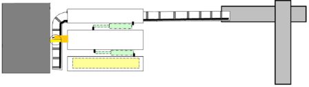
Figure 1 – Structure Coil PC top view
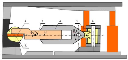
Figure 2 – Structure the tunnel boring machine for development workings in intensive excavation of thin layers
2.3. Select a block of the executive body
Sagittal executive body of the combine is a unit with an electric motor and gear cutting crown mounted in a U–shaped guide frame. With the help of two hydraulic cylinders, mounted in the frame, the unit may nominate her guide 900 mm, which allows to generate the rough section of 35 m2 and produce up to two notches in the crown slaughter without including crawler and lifting outriggers.
Boom turns cylinders combine the horizontal and vertical planes through a step change in flow entering the working fluid are used to move the boom in these planes with three operating speeds.
To intensify the working face and a more accurate way section of development, the executive body of the block is set by loading machine poddirochnoy MNR. Using such an actuator unit is based on its body structure such as the U–shaped frame of a telescopic boom with the actuator body pivotally around its axis. That allows to fulfill the slaughter at any angle and various forms section of development. As a tool for the destruction of the rock mass is used disc executive body. [15,13]
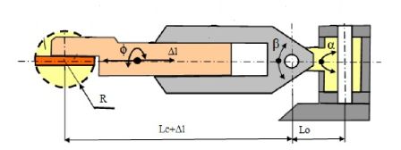
Figure 3 – Block Diagram executive body of the machine using the disk MNR
3. Improving the efficiency of
To analyze the impact of dredging intensity on the rate of formation of fine was calculated daily length of penetration depends on the daily performance on the layers of different power m = (0,5; 0,7) m.
The formulas:
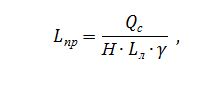
где:
Lпр – daily length of penetration, m / day;
Qc – daily combine capacity, t / d
Lл – lava length, m;
Н – power executed by the reservoir, m;
v – density of coal, t/m^3.
To estimate the required rate of penetration were calculated values ??according to the daily production of harvester (Figure 4 and Figure 5) when removing seams H = 0.5 m and H = 0.7 m for longwall Ll = Ll = 100m and 200m. [3,4]
We represent payment for the most daily output:
When Qc = 3000 t / day; Ll = 100 m; ? = 1,3; H = 0.5 m, and Lpr = 46.15 m, and if Qc = 3000 t / d; Ll = 200 m; ? = 1,3; H = 0.5 m - Lpr = 23.07, m.
When Qc = 3000 t / day; Ll = 100 m; ? = 1,3; H = 0.7 m, and Lpr = 32.97 m, and if Qc = 3000 t / d; Ll = 200 m; ? = 1,3; H = 0.7 m - Lpr = 16.48, m.
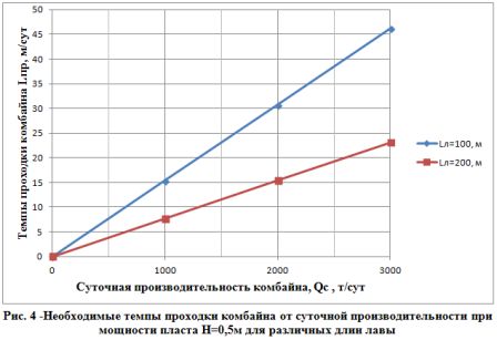
Рисунок 4 – Необходимые темпы проходки комбайна от суточной производительности при мощности пласта Н=0,5м для различных длин лавы
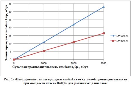
Рисунок 5 – Необходимые темпы проходки комбайна от суточной производительности при мощности пласта Н=0,7м для различных длин лавы
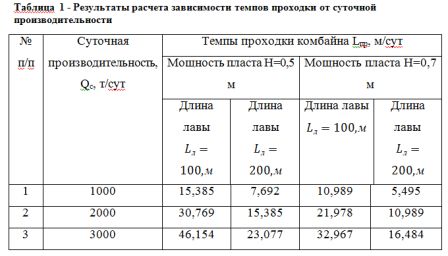
From the above calculation shows that the same values ??of the daily performance and length Qc Ll lava formations at different power values will differ significantly penetration rates Lpr. On this basis, it can be said that the intensive fine recess formations effectively applied lava Ll length = 200 m Since the time of installation and dismantling of equipment takes a long time, about one month, hence it is clear that with today's daily performance and speed of movement of shearers required daily output tunnel boring machine exceed 2000–3000 t / d and acceptable rate of penetration are Lpr = 23.077 m for the formation of H = 0.5 m and 16,484 m = Lpr in seams H = 0.7 m. [8,7]
Based on the analysis suggested the possibility of technological schemes for excavation thin bed:
Figure. 6 (a) is a schematic diagram for intensive excavation thin bed of lava ahead for preparatory develop, produce excavation carried out on 20–30 meters ahead of lava along the excavated post fossil. Muck scraper conveyor and transported produced rubble tab strip to temporarily maintain goaf roof rocks along the new–generation running the width of 5m. As you move the lava in the reconstruction shifts produced revision conveyor, conveyor transport dismantled drift and increase it to the conveyor in the ongoing advance working (after the tunnel boring machine).
Possible and laying rubble strips along the lava on the goaf for more secure fastening of the roof rocks.
In Figure 6 (b) is a schematic diagram for intensive excavation thin bed with preparatory production with a lag of 20–30 m from the lava. Also laying the Butovo strip along the slaughter line.
For the convenience of mounting and holding, production spend rectangular area of ??8.10 m^2. [11-18]
Calculate the length of the recess Post by the formula:
where:
Lст =2000 – Din excavated column, m;
Lпр – rate of penetration, m / day.
Reservoir capacity for H = 0.5 m long and lava Ll = 200 m, with the daily performance Qc = 3000t/sut:
Reservoir capacity for H = 0.7 m long and lava Ll = 200 m, with the daily performance Qc = 3000t/sut:
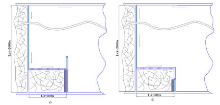
Рисунок 6 – Технологические схемы для интенсивной выемки тонкого пласта
According to the obtained maximum (for this work), the duration of the recess post results we can say that the time for assembly and dismantling takes for the former third pillar of the recess time, and in the second case – 1/4 of the time. On this basis, it is necessary to reduce metal miner, which will reduce the time spent on installation and dismantling of the BM. To solve this problem it is necessary to simplify the structure of the combine, by applying the new structure of the tunnel boring machine movement, whose role will be to carry out mechanized system.
After analyzing the data type of the combine efficiency (experimental work Stepanenko EY) during development working, we see that the time spent in shunting operations, occupies 85.86% of the time of the combine.
In connection with such a situation, there is a need to reduce the time of shunting operations, which will increase the rate of penetration. By achieving this goal is to improve the technical level of the BM
One of the ways to increase the efficiency of your PC is to increase their technical productivity by reducing time lost to downtime and idling cutting drive that can be achieved by equipping combine mechatronic supply system IO, realizing the combination of the two in time of his movements in mutually perpendicular directions, with computer controlled adaptive processing slaughter.[9,16]
Findings
One possible to secure high rates of penetration, is to reduce the time needed for shunting operations by improving the technical level of the tunnel boring machine.
Ability to combine operations to ensure alignment in time can significantly reduce the cycle time passing generation and reducing the time spent on installation and dismantling of the combine, and the possibility of passing the workings with high quality side surfaces and soil – will greatly enhance its efficiency by reducing the amount of backing. Ability to work in hard rocks combine with lower power consumption and higher performance.
To improve the technical level of the tunnel boring machine for effective penetration of development workings in intensive excavation of thin layers was proposed structure of the BM movement, which ruled the BM chassis. The proposed structure of the system move significantly changes the entire structure and the tunnel boring machine. In this scheme (Figure 2) shows that the government is set on the body mechanized system that simplifies the design of the harvester, reduces metal consumption and reduces the time spent on shunting operations. Transfer system harvester consists of three sections mechanized system that causes the BM movement along the slaughter line by advancing hydraulic jacks lining between the sections and the shifting of the scraper conveyor. Mechanized system supports the roof rock bottom, thereby increasing the stability of the combine. For simplicity, fixing the roof and the side surfaces of development workings, made recess erodible solid rectangular section workings.
List of sources
- Комплексная механизация и автоматизация очистных работ в угольных шахтах. Под общей ред. Б.Ф. Братченко. М., "Недра", 1977. с. 415.
- Горбатов П. А. Гірничі машини для підземного видобування вугілля. – Донецьк, 2006.
- Шабаев О.Е., Семенченко А.К., Хиценко Н.В., Семенченко Д.А., Степаненко Е.Ю. Повышение ресурса проходческих комбайнов с аксиальными коронками на основе регулятора нагрузки в системе подачи исполнительного органа // Наукові праці Донецького національного технічного університету, Вип. 16 (142), Серія: Гірничоелектромеханічна, Донецьк, 2008. – С. 265–274.
- Семенченко А.К., Шабаев О.Е., Семенченко Д.А., Хиценко Н.В. Принципы создания проходческих комбайнов как мехатронных систем // Наукові праці Донецького національного технічного університету. Серія: Гірничо–електромеханічна. Випуск 113. – Донецьк, 2006. – С. 238–243.
- Проектирование и конструирование горных машин и комплексов: Учебник для вузов / Малеев Г. В.; Гуляев В. Г.; Бойко Н.Г. и др. – М.: Недра, 1989.
- Семенченко Д.А. Обоснование параметров исполнительного органа проходческих комбайнов с аксиальными коронками: Дис. ... канд. техн. наук: 05.05.06. – Донецк, 2003. – 158 с.
- Горные машины для подземной добычи угля / П.А. Горбатов, Г.В.Петрушкин, Н.М. Лысенко, С.В. Павленко, В.В. Косарев. – Донецк: ДонНТУ, 2006. – 669с.
- Малевич Н. А. Горнопроходческие машины и комплексы. – М.: Недра, 1980. – 384с.
- Машины и оборудование для проведения горизонтальных и наклонных горных выработок. Под. pед. Братченко Б. Ф. – М: Недра, 1975. – 416с.
- Перспективы создания проходческих комбайнов нового технического уровня / Семенченко А. К., Шабаев О. Е., Семенченко Д. А., Хиценко Н. В. (Донецкий национальный технический университет) // Каталог–справочник "Горная техника – 2005"http://library.stroit.ru/articles/combain2/index.html.
- Ржевский В.В. Открытые горные работы. Часть 1 и 2. М., Недра.2005.
- Анистратов Ю.И. Технология открытой добычи руд редких и радиоактивных металлов.М.,Недра,2008.
- Брюховецкий О.С., Бунин Ж.В., Ковалев И.А. Технология и комплексная механизация разработки месторождений полезных ископаемых. М.,Недра,2009.
- Фомин С.И. Основы технологии горного производства.СПб.,2004.
- Справочник открытые горные работы. М., Недра, 2005.
- Кулешов А.А. Проектирование и эксплуатация карьерного автотранспорта. Справочник. Часть 1 и 2. СПб., изд. СПГГИ, 2005.
- Единые правила безопасности при разработке месторождений полезных ископаемых открытым способом. М., Недра, 2004.
- Вернер И.В., Мороз А.И., Симанович Г.А., Тарасенко А.А., 2000 г.