
Abstract
- Introduction
- 1. Relevance of the topic
- 2. Purpose and objectives
- 3. A review of research and development
- 4. Analysis methods of cleaning sump
- 5. Special airlift installations
- 6. Hydrotreating and calculation parameters airlift installation
- 7. Investigation of the solids in the water-flow airlift Conclusion
- Summary
- Source List
Introduction
One of the areas of technical progress in the mining industry is the development of hydraulic pipeline transport in which water flows or of water aero carry the particles of solid material. In mine hydraulic conveying means are special facilities and drainage hydrotreating, such as airlift various designs, Hydraulic slurry pumps, and so on. The use of these tools in mining operations - one of the most promising ways of comprehensive mechanization.
As shown and many theoretical and experimental studies in DonNTU et al. university, one of the most effective and efficient in terms of exploitation of pumping and hydraulic conveying is airlift setup.
Airlift is a hydraulic device for lifting a drop of liquid, or a drop of liquid and solid material by using compressed in the supercharger and mixed with a drop of this liquid air (gas, steam). Lifting airlift pipe can be located in the space both vertically and have a certain slope. Airlift plant for a variety of design modifications, which comes with a variety of tasks, conditions and field use. However, all airlift consist of basic structural elements that are shown in the animated Figure 1.
Figure 1 - Workflow airlift
(animation: 21 frame, 5 cycles of repetition, 108 kb)
1 - deliver air pipe, 2 - mixer 3 - suction unit, 4 - lift tube, 5 - air separator; Qp - air flow, Qe - supply airlift; Δhp - the excess fluid column during start-up; h - immersion mixer; H - height of the lift.
With airlifts extract minerals from the bottom of the flooded quarries, lakes, seas and oceans. Airlift systems allow to extract from a depth of 100 meters or more. Apply airlift at a number of the construction industry - to lift sand, gravel, etc.; iron and steel - for lifting slag, dross; Chemical - for transporting corrosive liquids. Widely used in many areas of industry due to their advantages over conventional pumps.
Advantages airlifts:
- simple structure and high reliability;
- significantly reduces the cost of hard work, increasing the safety of maintenance works;
- be transported pulp with a high concentration of solid ( 35-40 %), and large abrasive particles;
- very high efficiency ( 40%), comparable to the efficiency of the pumps;
- self-regulation on the flow;
- automatic control unit, and so on.
Disadvantages:
- need for adequate relative immersion ?> 0,15 ( for airlift usual design);
- relatively high energy costs associated with the operation of the compressor;
- inability to transport slurry in a horizontal pipe;
- complexity of modeling the processes occurring in hoisting pipe.
1. Relevance of the topic
Many mining companies actual problem is the introduction of funds hydrotreating dewatering containers such as a sump and sump preliminary.
Mined rock is loaded with a catchment tank for vehicles produced, often non-motorized way heavy duty with an increased risk of accidents; present extensive work.
Centrifugal pumps are commonly used for pumping contaminated water are scarce resource work.
All this makes it necessary to revise the existing technology works on cleaning and pumping sump tanks. At the same time the most important requirements for new or improved technology is: increasing productivity and ensuring deserted or close to the purification method catchment tanks.
Rationale for the ejector of airlift will allow more efficient use of compressed air to the airlift.
2. Purpose and objectives
The aim of this work is to validate the workflow settings for the installation of an air lift hydrotreated mine dewatering tanks, construction of flow characteristics to determine the rational parameters of the installation.
To achieve this goal, the following main tasks:
- Analysis of the technologically possible circuits and treatment of mine drainage tanks using airlifts;
- Calculation of the installation of an air lift for hydrotreating sump using a computer program for calculating; airlift system with ejector in air duct;
- Justify the cost-effectiveness of the operation of this air lift installation;
- Conduct a study of the motion of solids in the water- flow riser pipe and airlift;
- Develop automation installation of an air lift, but also consider the installation, maintenance and safety in the operation of air-lift units;
- Consider the genesis, improving treatment of mine water and mine water problems in general.
3. A review of research and development
In[1] there is the theory of operation, hydraulic design and construction of airlifts and their elements, the results of experimental studies of air-lift units. In [2,3,11] solved the issues of integrated systems for the use of airlift hydromechanized mining enterprises. In reference [4], the theory and methods of calculation of the basic types of inkjet devices. Book [5], highlights the results of research of mine water quality and purification. Developed physical and mathematical models workflow airlift source [6]. In [7, 8] shows the theory of operation and design of air-lift units for various purposes, the fundamentals of automation. In reference [9], the basic theory, calculation, operating data and special funds drainage hydrotreating. In [10] provides an overview of the airlift basic theory airlifts, hydraulic calculation, motion study of the solid fraction in the riser airlift.
4. Analysis methods of cleaning sumps
Sump cleaning can be done in several ways. Most cleaning methods characterized by high capital costs, the unreliability of the equipment and electrical equipment that has repeatedly been the cause of flooding sumps and idle mines. The main problem of serving sump is spilling coal and rock while driving and loading skips. Brought some solid shaft water.
The main symptom, reflected in the classification methods, is the kind of lifting the rock mass at the horizon of the sump pit bottom or directly to the surface. On this basis divide the two main ways: mechanical and hydraulic.
Mechanical way
Mechanical method of cleaning sumps is extremely widely used in operating mines. The essence of this method is that the mountain wakes mass issued to their destination by means of mechanized delivery or upgrades on the trunk (skip, bucket, trolley, etc.). To download the rock mass on the vehicle frequently used manual labor.
Hydro mechanized methods
Hydraulic cleaning method sumps envisages transporting rock mass using hydraulic elevator, coal pumps, slurry pump , airlifts or pump - air-lift units. It gives you the opportunity to ensure the sharing of one process link removal operations rock mass, sludge from the sump and pumping sump influx.
Airlift method
In the mining industry airlifts of various designs used for major and minor drainage facilities to clean mine tanks (sumps, wells, etc.).
When applying airlift lifting rock mass is accumulated in the catchment of the sump, where it is organized airlift fence suction device. Transported to the pulp dewatering screen, after which the firm goes into the hopper of the main lift and issued to the surface.
Analysis of the conditions of mine drainage tanks shows that the air-lift installation must meet the following requirements:
- Ensure an effective job of hydro mechanized remove solid material and pumping water inflow at depths of up to 3m immersion mixer, rising with the slurry to a height of 50m;
- Flow part airlift should provide passage in the riser throughout the rock mass, received in a container with pieces of solid material largest size;
- Have a supply that provides a transport speed of the slurry in the riser.
5. Special airlift installations
The disadvantage of the hydraulic regime of air-lift units of conventional design, with a depth of immersion mixer h < 3m and α<0,15, even under conditions corresponding to the top of the flow characteristic (at maximum flow) is the presence piston structure -liquid mixture in the riser airlift. It is known that when such a structure, the gas - liquid mixture flow magnitude of pressure fluctuations in the riser duct and the air lift has a maximum value, which leads to the appearance of the reverse currents of liquid in the riser construction and installation of mechanical vibrations.
Special installation airlift can be used constructively - different schemes, such as:
Airlift jet apparatus with elements
Air lift installation equipped with the elements of the jet mixer apparatus (Figure 2) comprises the lifting duct 7, the air duct 8 connected to a cylindrical manifold 2, which nozzle 4 installed with a conical base formed as a grid 3, the inlet pipe 1, a cylindrical mixing chamber 5. Mixing chamber comprises an initial portion 9 and the transition portion 6. Outlet section of the feed pipe 1 are coplanar with the base of the conical transition of the nozzle 4 at the initial portion 9 of the mixing chamber and forms with it an annular inlet gap of the compressed air in the mixing chamber. Mixer design helps streamline the creation and management structure of the velocity field of the compressed air before entering the ring chains; allows to use the kinetic energy of the compressed air in the annular gap.
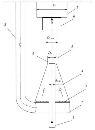
Figure - 2. Scheme of the mixer elements jet apparatus
Vacuum - airlifts
As an independent source of energy can be used to airlift the vacuum pump. These settings are at work do not require geometrical immersion mixer under the liquid level.
Vacuum airlift (Figure 3) works as follows: vacuum pump 7 installed in the underground environment, a vacuum and under atmospheric pressure lower part of the riser pipe is filled with slurry 4. Influenced by pressure difference between the tubing 3, the air from the atmosphere enters into the vacuum mixer 2 airlift. Moving under the action of the vacuum up the riser, the air does the work to raise the slurry to an air 6. Slurry through the hydraulic valve 5 enters into the transport system.
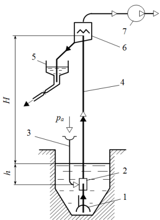
Figure – 3. Vacuum airlift
Air-lift system with ejector in the air duct
For increasing the efficiency of air-lift installations at depths of immersion mixer airlift not exceeding 70m, it is advisable to apply the air ducts on the ejectors airlifts. Excessive pressure in the pneumatic system of the shaft, usually 0.5 ... 0.6 MPa, which can be 10 times higher than necessary for the pressure of the air lift. Throttling the flow of compressed air regulating valve leading to unnecessary loss of energy , thereby reducing the efficiency of the installation . Therefore, using the excess pressure in the pneumatic system, developed in DONNTU airlift system with ejector in the air line (Figure 4). In 11 of the ejector diffuser excess potential energy of compressed air in the compressor 6 is converted into kinetic energy of the flow. Due to the high velocity jet of air expiration, a reception chamber 2 of a vacuum and under atmospheric pressure, it enters the air. Next, the mixed flow of air through the air enters the mixing chamber 5. Mixture enters the air separator 7 through the riser pipe 4.
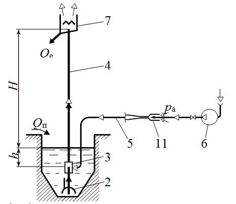
Figure 4 - Schematic of an air lift installation with ejector in the air duct
The main conclusions are as follows:
1. Airlift purification schemes improve the performance (compared to mechanical methods) to 15-25 times.
2. Such installations are most appropriate in preventing breakthrough slurries and liquidation of consequences of this.
3. Airlift purification scheme benefit from the economic and sanitary point of view better than others to decide whether the elimination of heavy manual labor.
6. Hydrotreating scheme and calculation of parameters of an air lift installation
We have made a calculation of the basic parameters of an air lift installation for hydrotreating sump skip shaft (mine conditions for "October Mine" DUEK GP).
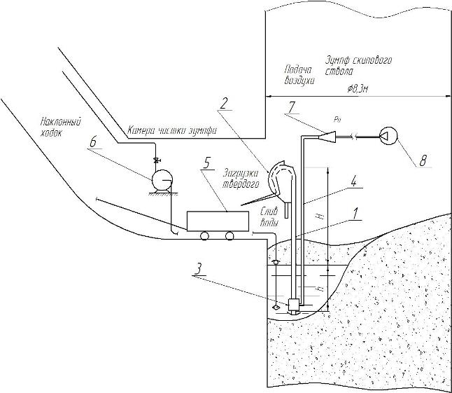
Figure 5 - Hydrotreating scheme skip shaft sump
The air supply pipe 4 at which compressed air is supplied to the mixer 3 airlift; pulp moves through the riser 1, passes through an air - arc sieve 2; 5 - skip special design; 6 - dewatering pump ЦНС 60 *150; 7 - ejector air duct; 8 - compressor.
Calculation of basic parameters of the installation of an air lift
Initial data for calculation are:
• immersion mixer, h = 3m;
• geometric height of the pulp, H = 10m;
• slurry feed rate, Qe = 25 m3/h;
• maximum diameter solid, dт = 0,05 m;
• the average density of the solid, ρтв = 2000 kg/m3;
• optimum volume concentration of solids in the slurry, S = 0,2;
• the work time airlift, T = 1h/day.
Energy characteristic determined airlift efficiency is the ratio of useful power to raise the slurry to power the air feed


where Nk - the useful power; Np - flow rate of air introduced into the mixer, the ηe - efficiency of the air-lift.
During this calculation, be prepared basic installation options, the principal of which are consumables and energy characteristics
Characteristics are constructed airlift
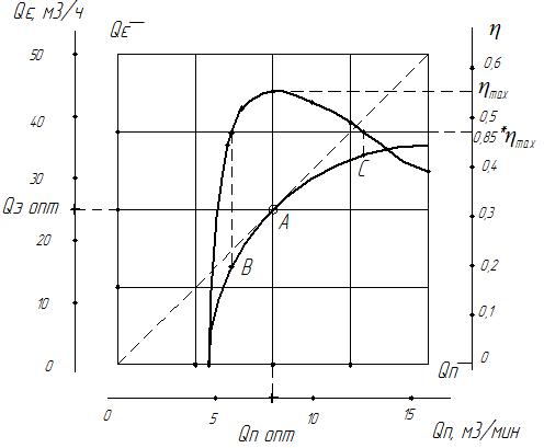
Figure 6 - Flow and energy characteristics of airlift
Point A corresponds to the optimal mode of installation, (B - C ) - a work area flow characteristics.
During the receipt of the following calculation parameters optimal operation of an air lift installation
Air consumption (at maximum efficiency) Qp = 8,26 м3/min;
Submission airlift, Qє = 25.6 м3/h;
Efficiency airlift, ηemax = 0,555.
This air lift installation for optimal air flow, it is proposed to use the ejector in the air duct. On most mining enterprises, in the absence of a developed pneumatic, to supply such airlifts, considered rational use of portable compressors such УКВШ. In particular, the smallest of sizes, compressors УКВШ 5/7, which has a 5 m3/min air flow and creates air pressure 7 kgf/cm2, significantly higher than necessary for the operation of this airlift - 1.5... 2 kgf/cm2. Power compressor motor УКВШ 5/7, N = 37 kW. Ejector air channel will allow to use the excess pressure in the pneumatic system for atmospheric air and create the desired mode for optimal air flow, Qp = 8.26 м3/min. In the master's work calculated the parameters of the ejector duct.
7. Investigation of the solids in the water-flow airlift
In designing systems for the air-lift lifting the solid material is a very important task of keeping a predetermined flow rate of water-air mixture (transport rate) in the supply conduit and the lift which must be above the critical value.
During the experiment, the specific air flow q changed by setting different relative immersion α, the value of which ranged from 0.101 to 0.405. Airlift transported solids of different shapes (sphere, cube, plate), volume and density.
These studies allow us to calculate the minimum allowable flow rate for the transport of solids in the riser airlift, which can be defined as:

Coefficient of resistance to movement of the solid with the minimum allowable speed transport

where RT - hydraulic radius, taken as the characteristic dimension of the solid.
Studies have shown that for every solid has its own point on the flow characteristic airlift, in which it is able to exit the riser pipe.

Figure 7. On the characteristics of airlift supplies shows the points at which the balls of different size and density out of the tube
Analysis of these characteristics yielded some motion parameters of the slurry in the riser airlift and build experimental dependence.

Figure 8. Experimental dependence of the minimum allowable speed transport of specific air flow related to the medium-pressure slurry, VТр = f (qп)
The study obtained values ??of the coefficient of resistance to movement, allowing you to measure the speed of the necessary transport slurry.

Necessary average rate in the riser airlift transport for solid determined by the equation.

where K3 - the safety factor; Кk - coefficient taking into account the concentration of the mixture; Кc - factor considering uneasiness.
Summary
Hydraulic diagrams of the purification process to deliver high reliability and performance, with beneficial economic and technological points of view and better than others to decide whether the elimination of heavy manual labor. Design diversity airlift units makes them versatile for use in a variety of conditions. In designing the air-lift units for lifting solid material is a very important task of maintaining a predetermined flow rate water mixture.
In writing this essay master's work is not yet complete. Final completion: December 2014. Full text of the work and materials on the topic can be obtained from the author or his manager after that date.
Source List
- Энциклопедия эрлифтов /Папаяни Ф.А., Кононенко А.П., Козыряцкий Л.Н. и др.– Донецк, Москва:
Информсвязьиздат
,1995, – 598 с. - Гідромеханізація: навчальний посібник. М.Г. Бойко, В.М. Моргунов, Л.М. Козиряцький, О.В. Федоров. – Донецьк: ДНВЗ
ДонНТУ
, 2011, – 554 с. - Ерліфти та гідроелеватори в гірничій промисловості. Навчальний посібник. Козиряцький Л. М., Моргунов В. М., Яковлєв В. М., Геммерлінг, О. А. Донецьк – ДонНТУ. 2012, – 134 с.
- Соколов Е.Я., Зингер Н.М. Струйные аппараты. – 3–е изд. М:. Энергоатомиздат, 1989, – 352 с.
- Монгайт И.Л., Текинидзе К.Д., Николадзе Г.И. Очистка шахтних вод. М.,
Недра
, 1978, – 173 с. - Кононенко А.П. Рабочий процесс эрлифта и его моделирование. Монография. – Донецк: ДонНТУ, 2010, – 171 с.
- Методические рекомендации по применению средств механизации очистки шахтных водосборных емкостей// В.Г.Гейер, В.С.Дулин, В.И.Лазаренко, В.М.Яковлев. Донецк, ДПИ, 1983, – 50 с.
- Эрлифтные установки: учебное пособие// В.Г.Гейер, Л.Н. Козыряцкий, В.С. Пащенко, Я.К. Антонов. Донецк, ДПИ, 1982, – 63 с.
- Малеев В.Б., Данилов Е.И., Яковлев В.М. Специальные средства водоотлива и гидромеханизированной очистки шахтных водосборных емкостей: Учеб. пособие. – Донецк: ДПИ. 1986, – 36 с.
- Бойко М.Г., Козиряцький Л.М., Кононенко А.П., Землесосні та ерліфтно – землесосні снаряди: Навч. посібник. – Донецьк: ДонНТУ, 2005, – 296с.
- Антонов Я.К., Козыряцкий Л.Н., Малашкина В.А. и др. Гидроподъем полезных ископаемых. – М: Недра, 1995, – 225 с.
- Кононенко А.П. Теория и рабочий процесс эрлифтов. Дис. докт. техн. наук. – Харьков: НТУ «ХПИ», 2007, – 565 с.
- Кононенко А.П. Структуры двухфазных потоков в подъемных трубах эрлифтов // Вісник Сумського державного університету. Серія – Технічні науки. – Суми: СДУ. – 2005. – №12(84).
- Кононенко А.П. Энергетическая эффективность эрлифта / А.П. Кононенко // Науковий журнал
Вісник Донецького університету
. Серія А,Природничі науки
. Донецьк: ДонНУ. – 2006. – №1, Частина 1.