
Abstract
NOTE: Summary staging is nature, as when it was created – April – May 2014, while the defense of master's work is scheduled for January 2015
Content
- 1. Relevance of the topic
- 2. Objective, methods and objectives of the study
- 3. Analysis of the current state of research question
- 3.1. Classification analysis the connection details in the form mating surfaces
- 3.2. Analysis of the use of detachable joints used in the machine - and instrumented
- 3.3. Analysis of the use of non-detachable joints used in the machine - and instrumented
- 3.4. Analysis principles layout rotor lines
1. Relevance of the topic
Given the development of production towards the production of diversified raznoseriynomu need to improve the performance due to the synthesis of new technologies through the use of an extended number of new machinery. For assembly work in total engineering production characterized by a tendency to constantly improve production and production capacity in general assembly[1].
Assembly is the final stage of manufacturing machines, largely determines its performance, as in the assembly process for various reasons may arise error mutual arrangement of parts and assemblies. Same precisely manufactured parts under different conditions can change Connection durability of machines hundreds of times [2].

To improve the quality of assembly, increase productivity and improve the economic efficiency of the entire assembly process must be found new ways of non-standard tasks. This principle effectively applied such species as the central assembly (subassembly or assembly), the by moving an object collected can not be prevented, as well as break into the assembly operation nodes. This principle has been developed and a modular principle.
Using modular technology to assemble new opportunities not only increase productivity, but also on a number of products with a build quality – economic effect.
2. Objective, methods and objectives of the study
The purpose of the master's work – improving build performance products on rotary lines based on modular technology. Development of technological equipment in the assembly based on the use of modular technology.
The object of research are compounds with a clearance, and also the landing and transitional shape mating surfaces.
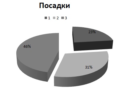
Analysis of the use of the compounds and landings in mechanical engineering on a global scale is given below in Figure 2:
Subject of research – technological support product assembly, rotary transfer lines as well as the characteristics of the assembly process using modular technology.
The proposed modular design manufacturing processes of products based on the concept of structured products as a set of modules and connection modules surfaces opens new perspectives in solving the problem of improving assembly production.
It allows you to develop a unified approach in the design of assembly processes, means of implementation broad introduction typing, harmonization and standardization.
At the heart of the assembly process of any product is primarily a process of its connection parts, subassemblies. This process is an integral part of the assembly process and is its basis. It is this part of the build process first determines the efficiency of the entire production process and requirements to the means of mechanization and automation [1].
Connection of parts, assembly units occurs through a combination of their bases, which are mainly basing modules surfaces (BCH). MNR also represents a combination of two BCH – direct and counter him when the product does not work, ie the compound is converted into the movable stationary.
This happened in the presence of relative motion of the parts of the BCH, which formed compound ( MS), go to the category of Natural Resources. Here we should note another circumstance published trajectory of the module relative to one another is provided by the respective surfaces from MNR acting as bases, whose task it is depriving parts of the corresponding degrees of freedom.
Same initial data for the development of modular manufacturing process does is it drawing a modular representation and production volume. Therefore, before developing a modular process, it is necessary to introduce a set of MP detail.
However, MP, are listed in the classification by design, as its constructive- geometrical design and characteristics reflect the requirements of the service destination details.
At the same time, the analysis shows the various parts that they meet the surface, do not belong to based, work or binder MP. This is explained by the fact that the manufacture of parts laws technology, whereby parts necessary to provide various kinds of additional surface to facilitate its manufacture.
Such surfaces, improving those illogical details will be called technological and conditions apply to the class of their MPS.
However, from the standpoint of technology manufacturing parts in some cases it is desirable to combine such MP MP with other groups, known as integrated modules surfaces ( IIP).
Therefore, in those cases where some MP combine the IIP should make appropriate adjustments in the detail drawing.
In accordance with this, in general, the detail drawing in a modular design can be represented by a set of only MP or MP or only MPI with MPI [1].
3. Analysis of the current state of research question
3.1 Classification analysis the connection details in the form mating surfaces
The share of assembly operations in total engineering production ranges from 25 to 40%, and Instrumentation industry reaches 70%. In the experimental production of these figures are doubled [1].
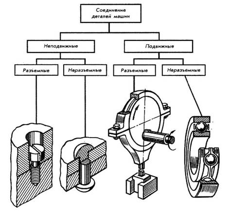
Classification of compound parts used in machinery and instrument, usually divided into mobile, providing details on the movement of one another, and still, in which two or more parts are rigidly attached to each other [3].
Types of compounds items (Figure 3); Classification of compounds items (Figure 4).
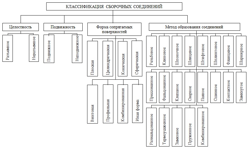
In turn, according to the scheme of classification of compounds form assembly mating surfaces is:
– flat
– Cylindrical
– conical
– spherical
– helical
– profile
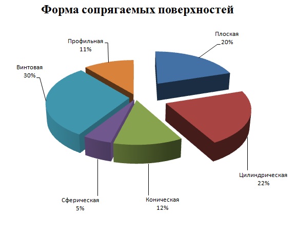
Analysis of the shape of mating surfaces provided below in Figure 5:
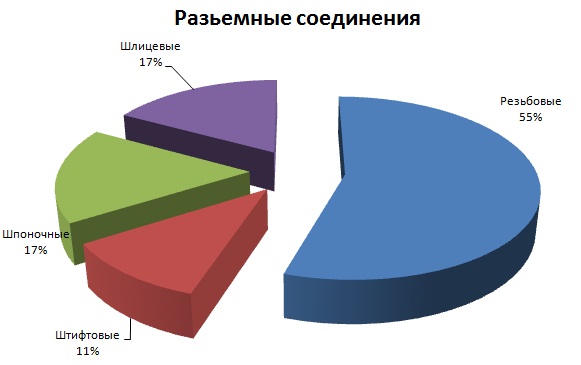
3.2. Analysis of the use of detachable joints used in the machine – and instrumented
Each of these two types of connections are divided into two main groups: detachable and permanent. Detachable called such compounds, which allow multiple assembly and disassembly assembly unit without damaging the parts. To split a fixed connections include threaded, Finger, keyways, splines, as well as compounds implemented transitional plantings. Plug mobile connections have movable landing (landing clearance) for cylindrical, conical, screw and flat surfaces [3].
Analysis of the use of detachable joints provided below in Figure 6:
3.3.Analysis of the use of non-detachable joints used in the machine – and instrumented
These are called non-releasable connection that can only be disassembled by destruction of residual strain or invalid one of the structural elements. One-piece fixed connections are made by mechanical means (press fit, riveting, zagibkoy, punching and stamping) by physico-chemical forces of adhesion (welding, soldering and bonding) and by immersing the parts in molten material (zaformovka into molds, the molds and etc.) [4].
The percentage of using the compounds shown below in Figure 7:

3.4. Analysis principles layout rotor lines
A variety of automatic lines are rotary automatic lines designed L.N.Koshkinym engineer.
Rotary lines are one of the highest forms of automation of technological processes, as inter-machine inside the machine and transporting workpieces flow is carried out continuously at a constant speed, which facilitates the management of performance and quality of processing. Automation of production processes involves complex scientific and technological development activities intensified technological operations and creation on their basis of efficient equipment, performing basic technological and auxiliary operations without human intervention.Different levels of automation degree of coverage of the main and auxiliary operations of the production process.On the basis of rotor lines has a comprehensive automation of manufacturing processes including machining of parts stamping and machining, assembly, packaging, kitting, labeling and packaging. Experience shows that for certain types of production workshops, the creation of machines equipped with only an automatic rotary lines, gives a significant economic impact [5].
Automatic rotary line consists of working rotors and rotor transport, transmit workpiece from one work to another rotor (Figure 8).
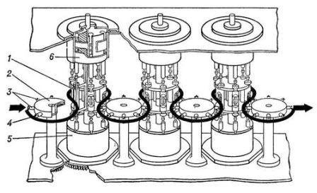
Work is a rigid rotor system, which is mounted on a group of guns, evenly spaced around a common rotating shaft system. Necessary labor movements reported that implements executive bodies for small mechanical forces applied executive bodies for large – hydraulic (eg, stocks hydraulic jacks).
Instrument, usually mounted in a pre-establish Complete (outside working machines) blocks interfaced with the executive bodies of the rotor only predominantly axial coupling, allowing quick replacement units. Transportation rotors take, transport and transfer products.They are drums or discs fitted with bearing bodies. Most apply simple transport rotors having the same transport speed, and a common plane conveying objects of processing the same orientation. For transferring articles between workers with different rotors stepping distances or different positions of objects are processing transport rotors, which can alter the angular velocity and position in space transported items. Transport workers and the rotors are connected to a common line synchronous drive conveying each rotor one step at a time corresponding to the line rate [7].
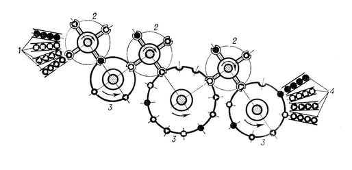
On automatic rotary lines can perform operations, significantly different in duration, such as compaction, control, thermal and chemical. Automatic rotary line can handle several different products. Such diversified automated rotary lines can be used in non-mass productions (Figure 9).
Automatic rotary lines can work on so-called reflex PATTERN providing operation of every organ in accordance with the control command by one of several provided by law (for example, to stroke or reject). Reflex sequences allow the machine to react without stopping at the various deviations from the normal course of work, such as the delivery of substandard object, cut parts during assembly, etc. [6].
4. Analysis principles layout rotor lines
Was further developed by the use of modular technology assembly processes under conditions of continuous systems.
Сonclusions
Ongoing scientific research to improve the engineering production differ fragmentation, lack of general ideas, fragmented and different approaches, methods and tools to solve them.
All this leads to duplication of effort, dispersion of forces, lack of focus on the main lines, in some cases, incompatible development.
As a result, the development of engineering industry as a whole takes place largely spontaneous, irrational, unevenly, with some problems can be solved adequately, others partially, and some little hesitant; On the other hand, numerous developments imponderable that makes engineering boundless, and the process of its development – unmanageable.
From the above it follows that the main task is not so much in search of new technological and technical solutions to ensure the assembly process for rotary lines, as in not the standard approach in addressing the problem.
Can solve this problem only with the new ideas, able to provide a solution for all the components of the problem. This idea is the use of modular technology in the assembly on rotary lines, as this technology provides increased productivity, economic impact and quality leap assembly process machine parts.