
Abstract final work on the topic
Contents
- Introduction
- 1. Known devices
- 2. Feasibility of creating this device
- 3. Device description
- 4. The principle of operation of the dispenser
- Conclusions
- References
Introduction
One of the areas of development and modernization of the equipment of continuous casting machines (CCM) intended for further manufacturing sheet metal work is to increase the maximum width and thickness of the slabs that are cast on them. In several foreign steel mills currently successfully operated caster for slabs up to 3250 mm wide. The thickness of the preform can reach from 150 to 355 mm.
Implementation of modern technology for continuous casting of steel involves the use of high-caster slag-forming mixtures (SCO) fed into the mold in order to stabilize the work mold oscillation mechanism and improve the conditions for the formation of a continuous ingot.
These circumstances, as well as the need to reduce the number of staff on site caster draft new generation employed directly hand feed SCO led to start working on a mechanical feed systems SCO metal mold on a mirror at a rate corresponding continuous ingot pulling rate. In most cases given mass flow SCO administered in powder or granular form, provide the body with hands down and moves along the mold, which drives, thanks to current converters allow to smoothly change the speed and flow characteristics of the metering system.
1. Known devices
The invention relates to metallurgy, in particular to devices for dispensing bulk powder and granular mixture into the mold slab continuous casting machine (CCM).
A device for dispensing powdered slag-forming mixture comprising a sealed bin with a given volumeslag-forming mixture , which dispensed by means of a feeder mounted inside the hopper and consisting ofdrive motor and gearbox output shaft which is connected via a coupling shank vertical shaft ,mounted in bearing supports and bearing on the lower end of the screw, wherein the screw portion of the screw is in the hopper , and the remaining- In the adjacent mixing chamber connected to the pneumatic conveying [ JSC " Chermetinformatsiya ". Bull." Metallurgy ", 2011 . - № 11. - P.39 ] .
The disadvantage of this device is that it can be used to provide feed mixture slagging only moldscasting billets small section ( varietal and bloom caster ) . The system involves the use of two feedenergy sources : electric and pneumatic , which complicates its operation and maintenance due to the need for specialDevice for drying carrier gas . Furthermore, when it is increased dust release operation occurs , and this eliminatesthe possibility for fine blends that are widely used in the continuous casting of steel.
The closest technical essence to the claimed solution is a device for continuous dispensing slaggingthe mixture into the mold slab continuous casting machine comprising a stationary hopper placed consumeda powdered or granular mixture , provided at its lower portion receiving chamber connected flexible metal sleevewith an inclined feed toe motor with gear to rotate the vertical shaft , the bottom of which is mounted coaxially with the shank inreceiving chamber and is rigidly connected to a steel spiral placed for relative rotation in the flexible metal hosesalong its entire length , and inclined feed sock attached to the carriage , having the ability to move through the gear motor ona horizontal beam , a vertical axis by hinged in its middle part at the end of the pivot bearingconsole and having the opportunity of plane motion in the horizontal plane relative to the broad wall of the wallmold [ Metallurgical processes and equipment in 2013 . - № 4 . - S. 75 - 77 ] .
The essential features of the known device, coinciding with the features of the device:
The disadvantage of this device is that the motor-reducer which moves the carriage, is fixed directly on it, i.e. during its movement along the broad wall of the mold is in a zone of intense thermal radiation, and the electrical cable, supplying power to the drive motor, during operation executes a motion in space along a complicated trajectory causing subjected to bending loads acting Poston, which significantly reduces the reliability of the device and the safety of its operation.
2. Feasibility of establishing this unit
The basis of the invention is to improve the reliability and safety of operation of dispensersfine materials into the mold slab continuous casting machine , which , by placingDrive gearmotor moving carriage at a distal end relative to the pivot-arm and to provide transfer of the moldtorque from the gear mechanism to move the carriage by a shaft and bevel gear pairs , excluded intensivethermal vozdestvie the motor side of the liquid steel located in the mold and moving the supply cablespace, causing his breaks
The problem is solved in that the device for continuous dispensing slagging mixture into the mold slab machinecontinuous casting of billets , comprising a stationary hopper with a consumable disposed powdery or granular mixture , equipped with aits lower part of the receiving chamber , a flexible metal conduit connected with an inclined feed toe with gear motor for rotationvertical shaft , the bottom of which is mounted coaxially with the shank in the receiving chamber and is rigidly connected to a steel spiral placed with the possibilityrelative rotation in a flexible metal conduit along its entire length , and inclined feed sock attached to the carriage , having the ability to movewith a geared motor located on the horizontal beam , a vertical axis by hinged in its middle part at the endbearing swivel arm and having the opportunity to plane-parallel movement in the horizontal plane relative to the broad wallmold according to the invention , the console is made hollow and geared motor mounted at the distal end thereof from the moldand a shaft connected with a shaft mounted in bearing supports in its cavity and provided with a bevel gear meshedconical wheel having rotatable about a vertical hinge axis disposed horizontally connecting beamand a console , and also meshing with the bevel pinion shaft , mounted in bearings on a horizontal beam and associated with the carriagerope means that one turn encircles it and is attached at its ends to two opposite sides of the carriage.
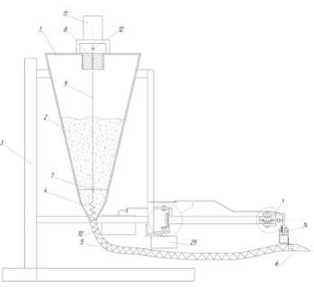
FIG. 1 shows a side view of an apparatus for dispensing a continuous slagging mixture into the mold slab continuous casting machine.
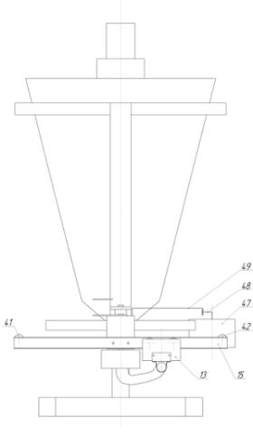
FIG. 2 shows a front view of an apparatus for dispensing a continuous slagging mixture into the mold slab continuous casting machine.
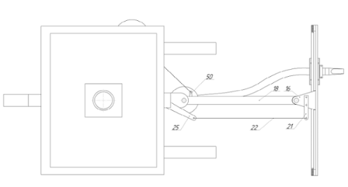
FIG. 3 shows a top view of an apparatus for continuous dispensing the mixture into the slagging mold slab continuous casting machine.
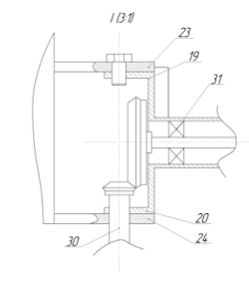
FIG. 4 shows a bypass element I in Figure 1.
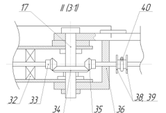
FIG. 5 illustrates remote unit II in Fig. 1.
3. Device description
The proposed device comprises a hopper 1 with a mixture of two consumable rigidly mounted on a metal structure and provided with a 3in the lower part of chamber 4 associated flexible metal sleeve 5 with an inclined feeding toe 6. Inside the hopper 1 into the bearing supports 7 and 8mounted vertical shaft 9 of which lower shank coaxially arranged in the chamber 4 and is rigidly connected with a steel coil 10 , disposedcapable of relative rotation in a flexible metal sleeve 5 along its entire length. At the top of the hopper 1 set gearmotor 11 ,which by means of coupling 12 is connected to the vertical shaft 9 . Inclined feed sock 6 is secured to the carriage 13 having the opportunityreciprocating roller 14 in C-shaped rails horizontally disposed beam 15. this barvia its associated rigid arm 16 and a vertical shaft 17 is pivotally mounted at its middle portion at one end of a hollow carrierthe pivot-arm 18 to the second end of which by means of two vertical pins 19 and 20 attached to the metal 3 . the bracket 16 is rigidlyattached to the lever 21 by a rod 22 and the pins 23 and 24 are pivotally connected with the metal element 25 3 . Dimensions element 25 rods 22 , the lever 21and pivot arm 18 are chosen so that they together form a parallelogram mechanism by which beam 15 is ablea plane- parallel movement in the horizontal plane relative to the wide wall of the crystalliser 26 , from which the tundish 27 through the dip glass 28 enters the molten steel . To move the carriage 13 along a horizontal beam 15 of the gear motor 29 mounted on the far After the mold 26 and the swing arm 18 associated with the shank of the shaft 30 mounted in bearing supports 31 and 32 in the cavity of the console. On the other shank of the shaft 30 is rigidly fixed bevel gear 33 meshing with a bevel gear 34 having a rotatable about a vertical axis 17 , which connects the beam 15 and bracket 18. bevel gear 34 meshes conical gear shaft 35 mounted in supports 36 and 37 for the horizontal girder 15 and is rigidly provided with two discs with clearance zakreplennmi 38 39, between which it encircles one coil cable 40 enveloping blocks mounted on axles 41 and 42, and attached to the tensioning screws 43 and 44 to two opposite sides of the slide 13 . At the ends of beams 15 arranged movable limit switches 45, 46 for reversing gear motor 29. The output shaft of the gear motor 47 mounted on rails 3 through 48 of the crank , the connecting rod 49 and pin 50 is connected to the swivel bracket 18.
4.Principle of operation of the dispenser
The device operates as follows. Before you start casting hopper 1 is filled with a mixture of 2 shlakooborazuyuschey and to adjust the positioninclined feeder sock 6 relative to the front wall of the mold 26 wide so as not to sock being touchedin the mold casting nozzle 28 of the tundish 27. Said adjustment is made by turning the hollow on the console 18vertical fingers 19 and 20 with a geared motor 47 associated with it by the crank 48, a rod 49 and pin 50 . Due tothat is rigidly connected with a steel 3 element 25 , Rod 22 , turning 18 and lever arm 21 form a parallelogram mechanismby rotating the support arm 18 and arm 21 is rigidly associated with the bracket 16 to the beam 15 make plane- parallel movementin the horizontal plane relative to the wide wall of the crystalliser 26 and thereby provide the possibility of arranging it in parallel atrequired removal of beams 15 , depending on the desired thickness slab blanks , which is supposed to be cast . Then the limit switches 45and 46 mounted on the beam 15 opposite the narrow walls kristallizatoora 26.
After starting the stream of continuous casting machine, when the level of liquid steel in the mold 26 rises to the set level, Start exercise gear motor 11 is provided through the sleeve 12 rotatably installed in the bearings 7 and 8 vertical shaft 9.
Together with nine shafts will rotate rigidly connected with it steel spiral 10 . Rotating spiral 10 turns its upper part , located in the chamber 4 of the hopper 1 , performs sampling and slagging mixture via a flexible pipe 5 transports it toinclined feeding toe 6. Upon receipt of the start slagging mixture sock 6 on the mirror in a metal mold 26 rungearmotor 29, which starts to rotate the shaft 30 mounted in supports 31 and the console 32 in the cavity 18. Thus anchored at itsshank bevel gear 33 rotates about the vertical axis 17 of the bevel gear 34 , the transmissionkonicheskokomu rotation shaft pinion 35 mounted in bearings 36 and 37. Upon rotation of the pinion shaft 35 40 rope wrapped around its single loopbetween the discs 38 and 39 enveloping components 41 and 42 and connected by means of tension screws 43 and 44 to the carriage 13 will cause it to move onroller 14 with respect to the feed -toed 6 C- shaped guides a horizontal beam 15 along the broad wallcrystallizer 26.
Thanks installed at the ends of beams 15 sliding limit switches 45 and 46 are separated by a distance equal to the width cast slab blanks, and a switch mounted on the carriage 13 (conventionally not shown), the gear-motor 29 is reversed at the moment finding in the extreme positions of the carriage, whereby it makes reciprocating movement along a broad wall of the mold, providing feed into its cavity shlakooborazuyuschey mixture in continuous mode with a predetermined rate.
If necessary, the rapid replacement of faulty nozzle of course serial casting, as well as after its completion devicetransferred from the operating position to the parking position, which stops the motor drive gear 29 of the carriage 13 and rungeared motor 47, which, acting through the crank 48, the rod 49 on the console 18, povrachivaet it by an angle of 90° . When turning the console 18thanks parallelogram mechanism, beam 15 along with the carriage 13, making the plane-parallel movement relative crystallization 26 frees workspace near the tundish tundish 27 as shown.
Thus, due to the fact that in the disclosed device, the drive of motor-reducer 29 mounted stationarily on the opposite After the mold swing arm 18 is not subjected to intense thermal action on the part of the liquid metal, and the cable inlet to motor-gearbox power, not srovershaet movement in space, ie not subjected to bending deformation, improved reliability proposed a mechanical system and its simplified-Hour and operation.
Conclusions
Данное устройство собрано в лабораторных условиях, на нём неоднократно были проведены исследования, которые показали все его достоинства и простоту управления. Данный дозатор можно использовать на слябовых МНЛЗ, он отличается своей универсальностью и компактностью, а также экономит расход самой шлакообразующей смеси и расход энергии потребляемой на работу всех его механизмов. Обеспечивает равномерную подачу ШОС таким образом обеспечивая повышение качества стали.
References
- Металлургические мини-заводы: Монография/ Смирнов А.Н., Сафонов В.М., Дорохова Л.В., Цупрун А.Ю. – Донецк:2005. – 469 с.
- Комплексное использование высокоосновных теплоизолирующих, шлакообразующих рафинировочных и разливочных смесей при высокоскоростной разливке на слябовой МНЛЗ / О. Б. Исаев, В. В. Акулов, А.И.Троцан и др. // Бюллетень научно-технической и экономической информации «Черная металлургия» ОАО «Черметинформация». – 2007. - №7. – С. 25-31.
- Смирнов А.Н., Куберский С.В., Штепан Е.В. Непрерывная разливка стали: Учебник. – Донецк: ДонНТУ, 2011. – 482 с.
- Процессы непрерывной разливки: Монография / Смирнов А. Н., Пилюшенко В. Л., Минаев А. А. И др. – Донецк: ДонНТУ, 2002. – 536 с.
- ООО «НПКП Солотвин» - Производство теплоизолирующих и шлакообразующих смесей для современных МНЛЗ / С. В. Шлемко, С. В. Шостак, А. В. Пащенко и др. // «50 лет непрерывной разливке стали в Украине»: Сб. научн. тр. / под ред. проф., д.т.н. Д. А. Дюдкина, проф., д.т.н. А. Н. Смирнова. – Донецк: Изд-во «Ноулидж» (донецкое отделение), 2010. - С. 213 – 223.
- Зайцев А.И., Лякишев Н.П., Артуняк Н.А. и др. // Металлы 2005, №3, с. 3-15.
- Зайцев А.И., Лейтейс А.В., Либерман А.Л. // Сталь, 2003, №3, с. 70-74.
- Куклев А. В., Лейтес А. В. Практика непрерывной разливки стали. – М.: Металлургиздат, 2011. – 432 с. Ил.
- Зайцев А.И., Калмыков К.Б. // Труды девятого конгресса сталеплавильщиков. 2007, с. 638-644.
- Смирнов А.Н., Макуров С.Л., Епишев М.В. и др. // Металл и литье Украины, 2006, № 3. с. 55-57.
- A comparison of the mould powders used to cast slabs, billets and blooms / S.Sridnar, K.S.Mills, V.Ludlow ea // 3rd European Conf. on Continuous Casting, Madrid-Spain, October 20-23, 1998. - 246 Madrid:1998.-P.807-816.
- Einsatz von unterschiedlichen Gei?pulveren beim Stranggie?en von Vorblocken und Knuppeln / H.Abratis, F.Hoffer, M.Junneman ea // Stahl und Eisen. 1996. Nr.4. – S.85-91.247
- Шлакообразующие смеси ТСК для кристаллизатора МНЛЗ ЗАО «АзовЭлектроСталь» / М.А. Шумаков, В.В. Балакин, В.А. Шабловский и др. // Сб. научн. тр. конф. «50 лет непрерывной разливке стали в Украине» 4-5 ноября 2010.: Донецк.- С. 507 – 514.
- Snowdon B., Cooper G. Developments in continuous flux feed systems for continuous casters // AISE Steel Technology. 2000/ No.5. – P.40-42. 249
- Kwong A., O’Brien S., Zinni M. The design and Start-up of the Granular Mold Flux Feeder at Stelco Hiton Works Slab and Bloom Casters // 2000 Steel Conference Proceedings. – P.263-267.250
- Schrewe H.F., Pleschiutschnig F.P. 20 years supper low head continuous casting at Mannesmann // World Steel & Metalworkihg. – Dusseldorf: V.7, 1985. – P.81-96.251
- 252Production of super clean steel by slab continuous casting process / S.Uchida, T.Masaoka, H.Uchibori e.a.// Nippon Kokan Technical Rehort.№36. 1982/ - P.42-55.
- Параметры, влияющие на чистоту стали в непрерывнолитых заготовках/ А. Пальмарес, П. Дауби, П. Мюссе и др..// Чистая сталь. – М.: Металургія, 1987. – С.109-128.253
- Смирнов А.Н., Пильгаев В. М. Перспектива развития технологии и оборудования непрерывного литья заготовок для плоского проката // Металлургические процессы и оборудование. – 2009. - №2. – С. 13 -18.
- Опробование автоматизированной подачи порошковых ШОС в кристаллизатор слябовой МНЛЗ / В. В. Соколов, Д. Б. Фойгт, В. В. Липень и др. // Сталь. – 2004. - № 5. – С. 37 – 38.
- Еронько С.П. Опыт конструирования систем дозированной подачи шлакообразующих смесей в кристализаторы машин непрерывного литья заготовок. / ОАО «Черметинформация». Бюллетень «Черная металлургия». – 2011. - № 11. – С. 35-40.
- Дождиков В.И., Шеинфельд И.И., Бережанский В.Е. Комплексное исследование условий контакта непрерывного слитка со стенками кристаллизатора: Зб. Науч. Трудов ЦНИИчермет. Непрерывная разливка стали. – М.: Металлургия. 1989. С. 32-43.
- Разработка ШОС для нестационарных режимов разливки на сортовых МНЛЗ / Д.Б. Фойгт, А.В. Шукан, А.Н. Иванов и др. // Сталь. 2009. №4. С. 25-27.
- Дюдкин Д.А. Качество непрерывнолитой стальной заготовки. – К.: Тэхника, 1988. – 253 с.
- Информация с официального сайта компании Sert-Metal. [Электронный ресурс]. Режим доступа http://www.sert-metal.com SERT-Metal Flow Control.
- . С.П. Еронько /д.т.н./, А.Л. Сотников, А.А. Котелевец ГВУЗ «Донецкий национальный технический университет» (Донецк, Украина)В.А. Чеченев /д.т.н./Государственный институт подготовки и переподготовки кадров промышленности (Днепропетровск, Украина) Исследование и расчет энергосиловых параметров автономной пневмомеханической системы дозированной подачи шлакообразующей смеси в кристаллизатор МНЛЗ // Металлургические процессы и оборудование. – 2011. - №2. – С. 10 – 18.
- Разработка устройства для непрерывной подачи шлакообразующей смеси в кристаллизаторы слябовой МНЛЗ / С. П. Еронько, С. В. Шлемко, В. В. Акулов и др. // ОАО «Черметинформация». Бюллетень «Черная металлургия». – 2009. - № 4. – С. 36-38.
- Новые системы дозированной подачи порошкообразных и гранулированных шлакообразующих смесей в кристаллизаторы МНЛЗ / С. П. Еронько, С. В. Мечик, С. А. Бедарев и др. // Металлургические процессы и оборудование. – 2009. - №2. – С. 34-38.