
Abstract
Table of Contents
- Introduction
- 1. Theme urgency
- 2. The purpose, problems and scientific novelty of the research
- 3. The review of the developments and researches on a theme
- 3.1. At the global level
- 3.2. At the national level
- 3.3. At the local level
- 4. Development of mathematical model integrated haulage system with EBS
- Conclusion
- References
Introduction
The modern shearer itʼs a highly mechanized and automated mechanism, which serves for fossil minerals extraction, particularly for coal mining. Usage of shearers is the most effective and rapid way of coal mining, but also the most complicated to implement one. Mining machines are mechanisms, which have to be thoroughly automated in order to increase mining safety and minimize maintenance costs.
One of the main mechanisms of shearer is a haulage unit. There are known a few ways of realization of shearer haulage unit:
— according to quantity of haulage unit: one, two;
— according to arrangement of haulage unit: integrated haulage; remote haulage unit;
— according to type of haulage unit: by using chain, chainless (rake mechanism);
Currently a different types of shearers for working in a thin seams are in usage (e.g. UKD200–250, UKD300, 1K101U, K103M, KD85, K600, etc.) based on using of electromagnetic slip coupling (ESC). Since 2008 haulage unit of UKD200–250 includes automated electrical drives based on usage of electromagnetic brake slip (EBS) [6]. Such a drives have a number of advantages (pulling force increase, using of water cooling etc.), but at the same time automated control system (ACS) of such drive requires further works at their modernization.
1. Theme urgency
At the moment the mining of thin seams is being accomplished by mainly shearers, equipped by chain remote haulage unit (RHU), which has a number of disadvantages, such as:
— irregular motion oа shearer;
— unsafe working conditions for mine personal;
— maintenance long pulling chain unit;
Also ACS of RHU doesnʼt take into account fluctuation of static and dynamic characteristics of new drivers equipped with EBS, character of its loading and also increasing of demands to pulling force ofhaulage unit. Therefore the most modern design solutions are directed on creating of integrated haulage system in which the speed variator is EBS [4]. However the principal distinction of the system is presence of speed stabilization system. The ACS of haulage speed must take into account static and dynamic characteristics of newlycreated drivers with EBS. Besides power increase the solution given allows to get a number of advantages which improve cooling, reliability parameters and driver size decrease. In the context of driver control, its electromagnetic and mechanical inertance are significantly increased. On the other hand, an essential decrease of dependence of the field magnetizing coil inductivity EBS on control current occurred. It caused by decrease of magnetic core saturation rate within work range.
The existing ACS of haulage speed control doesnʼt take into account possibilities of dual-driving haulage system during the shearer work with the seams which have large angles of slope (up to 35o). Other significantproblem of drivers with EBS is a presence of surge of rotational moment at haulage unit electromotor startup. Combining of drives into one haulage unitsystem will allow solving the both problems.
2. The purpose, problems and scientific novelty of the research
The aim of the work is research and development of ASC of shearersdual–driving integratedhaulage system with EBS for the invariance of the system in relation to the influence of the angle of slop and eliminating of highly dynamic start–up regimes when you turn on the electric supply.
The main objectives of the research:
- To review and evaluate existing research and develop technical solutions in the field of automation of the shearers dual–driving integratedhaulage system with EBS;
- Develop a mathematical model of the shearers dual-driving integratedhaulage system, taking into account the factors that influence to the loadingof the shearer dual-driving integratedhaulage system;
- Implement the developed mathematical model by means of computer facilities;
- To conduct research and analyse the results obtained;
- Develop a control algorithm, structural and fundamental electrical circuit load and speed regulator.
The object of the research: Automated dual–driving integrated shearers haulage system with EBS.
The subject of the research: Static and dynamic electromechanical processes taking place in the dual–driving integrated haulage system.
Scientific novelty: A mathematical model of the dual-driving integrated haulage system, which takes into account the actual static and dynamic characteristics of modern haulage units with EBS.
This objective is accomplished by the starting–up of two drives on a common shaft, in the opposite reaction and creation of ACS of such system. Such a system will allow eliminating the torques urges when you turn on the supply electric motors and ensure complete manageability in the seams with angles of slope upto 35o.
3. The review of the developments and researches on a theme
3.1 At the global level
Thus the basic clearing cars which are used for coal mining, are combines with the built in removed haulage system on the basis of a frequency-operated drive. The development tendency coal mining combines from leading German firm Eickhoff Bergbautechnik [9] is indicative. The RHU in these combines has been realised with use winches, i.e. the combine moved by means of the traction rope attached to the case. However gradually Eickhoff Bergbautechnik has refused from such RHU, completely having translated the manufacture in the beginning on release of removed haulage system of coal mining combine with frequency–operated engine, and then and built in.
In our country and neighboring countries, for the moment, for the development of the coal industry such funds are released. Therefore, given the high cost of shearers with frequency-controlled drive, widespread shearers with RHU on the basis of electromagnetic slip clutch.
3.2 At the national level
Consider the application of the imposition of supply system (fig. 3.1) as an example of the shearer UKD–250. Driving engines are accordingly taken out on main transport road (are mounted on trailer sites of the conveyor). Sprocket-wheels are applied in role of driving elements of propeller. The general chain traction body is fixed with help of swivels to the case of the car and covers both sprocket-wheels on the conveyor ends. At work a lobby in the direction of a coal mining combine the subsystem moves a working branch of a chain, and back – tightens a single branch of traction body.
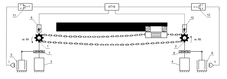
Figure 3.1 – Functional replacement scheme RHU shearer
At figure: 1, 2 – driving an sprocket-wheels of accordingly pulling and tightening drives of haulage system; 3, 4 – driving engines; 5, 6 – electromagnetic brakes of sliding; 7, 8 – differential reducers; 9, 10 – inductive distance sensors (speed sensors); 11, 12 – amplifiers on IGBT-transistors; АТ16 – the microcontroller of type ATmelMega 16.
3.3 At the local level
Scientific researches in the field of automation were carried out by such scientists as: V.Potsepaev [1][2], S. Dubinin [5], N. Boyko [8].
Master of DonNTU Alexey Sanchenko has realized researches on improvement of existing RHU control system, developing automatic control of both drives of haulalge system. Also necessity of application of more perfect speed sensors is based in work – distance sensors. But at composing of RHU model as a variator of speed has been accepted ESC. Besides, the developed device did not provide distribution of loadings between drives.
Master of DonNTU Sergey Gutsalyuk already engaged increase of operational efficiency of coal mining combine UKD–250 removed haulage system based on a rational parametres substantiation of the pulling and tightening automated electric drives. However, there also appears ESC, which also has a number of disadvantages mentioned above.
4. Development of mathematical model integrated haulage system with EBS
Based on the model of the feed drive, which as used in a speed EBS, presented in [3] was obtained by the model of the shearer with two integrated haulage system driver supply with EBS. For automatic control of speed and load shearer each equipped with its own feed drive EBS. Feed speed and traction change with an automatic adjusting the excitation current EBS. The model takes into account the actual static and dynamic characteristics of the drive, as well as the specifics of the new digital speed sensor drive star drive the integrated haulage system. Fig. 4.1 a mathematical model of the actual feed drive with EBS:
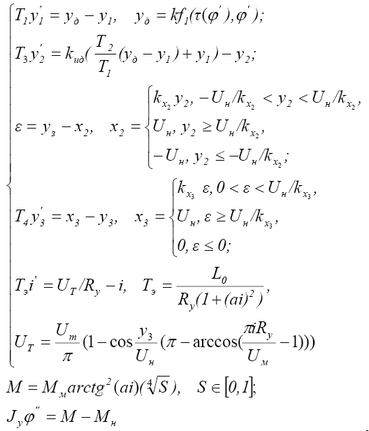
Figure 4.1 – The system of differential equations (1)
where T1–T4 – time constants corresponding dynamic element; Tэ – time response of the control winding EBS; yд – discrete output speed sensor with a conversion ratio k and time delay тау; фи — angle of rotation driver star; kид – gain integro-differentiating element; E – mismatch signal; kx2, kx3, x2, x3 – gain ratio and corresponding nonlinear outputs elements; Uн – limiting voltage output nonlinear elements; Uт – the output voltage of the thyristor converter; Ry – active resistancecontrol winding EBS; i – current control EBS; Um – amplitude sinusoidal voltage thyristor converter; M – electromagnetic torque EBS; Mk – critical torque EBS; a – empirical coefficient, taking into account the degree of saturation of the magnetic circuit EBS; Jy – torque of inertia of the rotating components of the transmission shown to drive a star; S – slip EBS; Mн – torque load attached to star drive.
In addition to the mathematical model of the feed drive was composed differential equation which describes the motion of the harvester with a mass [7]. Block diagram of the dual–driving integrated shearers haulage system with EBS (fig. 4.2). The model is implemented and studied in the environment SIMULINK.
Figure 4.2 – Block diagram of the dual-driving integrated shearers haulage system with EBS
f2(E) – gain direct circuit (K = 12). Restriction level defined upper level 10 range control signal phase shifter controlled rectifier (thyristor bridge or bridge on the power FET). Aperiodic element 1/T4P + 1 and nonlinearity Uт = f4(y3) simulates controlled rectifier. Time constant T4 equal to the duration halftime mains.
In the model, the control winding EBS L(i) – winding inductance control, which is due to saturation of the magnetic circuit is a function of current. This functional dependence is well approximated by the function: L(i) = L0/1+ai2, where L0 – inductance in the saturated magnetic circuit.
Nonlinear element M(i) reproduces the relationship between torque and drive the axis of a current control M(i) = Ммarctg2(ai), where Мм – maximum torque, determined by the design parameters EBS.
M(s) – dependence of drive torque from slipping. For a given design EBS this dependence is approximated M(s) =
![]() . Product M(i) on M(s) determines the static characteris
tics EBS: M(i,s) = Mмarctg2(ai)*
. Product M(i) on M(s) determines the static characteris
tics EBS: M(i,s) = Mмarctg2(ai)*![]() .
Mн – load torque applied to the star drive. Induction motor is simulated with constant speed
W0, which is consistent with the task.
.
Mн – load torque applied to the star drive. Induction motor is simulated with constant speed
W0, which is consistent with the task.
An integrator with a time constant 1/Jy reproduces the drive speed of the rotating masses. Jy – reduced torque of rotating mass drive inductor,wheelsets and shafting planetary gearbox, gear unit and mass harvester. When the gear ratio 192 and the total moment of inertia of the input transmission 0,15 kg*m2 reduced to the drive wheel moment of inertia: Jy = 5530 kg*m2.
Element y1 is the first link of the second order filter designed to filter interference from the mains voltage (T1 = 0,003 s), element y2 – is the sum of the real differentiator element T2P + 1/T3P + 1 and delay element of the first order 1/T3P + 1. Real differentiator element provides a positive phase shift of the feedback signal. Element 1/T3P + 1 and denominator real differentiator element are the second elements a second order filter. Gain kид sets out the measurement of the feedback signal from the angular velocity.
Simulate movement combine idling with different angles fall (fig. 4.3):
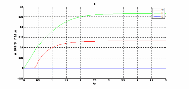
Figure 4.3 – Dependence of the rate filing shearer from the current at different fall angles
(animation: volume – 67 KB; size – 650х300; number of shots – 5; delay between shots – 1500 ms; number of repetition cycles – 5)
The figure shows how the speed of the combine and the current value on both drives, depending on the angle (0o, 5o, 15o, 25o and 35o). When the fall angle are 35o, speed of the combine is 0,25 rad/s, where in the first current (leading) drive is almost equal 0 А, and the current drive is the second 8 А. His suggests that the entire burden falls on the inhibitory drive. When driving a combine on a flat surface opposite occurs – current retarding drives s almost equal 0 А, that is the whole load on the leading drive. This suggests that the proper distribution of load between the drives of the system is completely controllable.
Conclusions
The structure is developed and investigated ACS of a shearer dual–driving integrated haulage system with EBS.
A scheme of opposite connection startup of haulage units is proposed, which is running on oneshaft, in order to in crease the control lability of the shearer in seams with large angles of slope and eliminating surges of torqueat haulage unit electromotor startup.
Later, at master's research work, will be performed the more detailed modelling of integrated haulage system with EBS, development of control algorithmand structural and principal electric schemas of feeding speed control system.
References
- Поцепаев В. В. Исследование динамики и выбор рациональных параметров вынесенного привода подачи очистных комбайнов: автореф. дисс. на соиск. уч. степ. канд. техн. наук. / Поцепаев В. В. — М.: ИГД им. А. А. Скочинского, 1986. — 14 с.
- Поцепаев В. В. Математическая модель вынесенного привода подачи комбайнов для тонких пластов //Научн.тр.ИГД им. А. А. Скочинского. - 1983. - Вып.218. - С.56-62.
- Дубинин С. В., Поцепаев В. В. Система автоматической стабилизации скорости вынесенного привода подачи с электромагнитным тормозом скольжения для горных машин. // Наукові праці Донецького національного технічного університету. Серія: Обчислювальна техніка та автоматизація. - Вип. 22 (200). – с.6 – 10.
- Дубинин С. В., Сидоренко И. Т. Применение электромагнитных муфт скольжения в приводах горных машин// Горн.электромеханика и автоматика: Респ.межвед. науч.-техн. сб.- Киев: Техника.1988г., Вып. 52- С.62-65.
- Дубинин С. В. Снижение динамических нагрузок и повышение эффективности вынесенной системы подачи очистного комбайна: Автореф. дисс.. на соиск. уч. степ. канд. техн. наук. / Дубинин С. В. — Донецк, 1991 г. — 209 с.
- Щетинин Т. А. Электропривод с индукционными муфты и тормозами. /Щетинин Т. А. — М.: Машиностроение, 1970. — 146-150 c.
- Горбовский И. В. Исследование САУ встроенной системой подачи с электромагнитными тормозомами скольжения очистных комбайнов / Гос ВУЗ «Донецкий национальный технический университет» / Матерiали: ХIV Міжнародна науково-технічна конференція аспірантів і студентів — Донецьк, ДонНТУ — 2014, Том 2, с. 121-123.
- Бойко Н. Г. Динамика очистных комбайнов. - Донецк: РВА ДонНТУ, 2004. - 206 с.
- CAN. CAN in Automation (CIA): Shearer loader mining vehicle [Электронный ресурс] / CAN. — Режим доступа к статье: http://www.can-cia.org/index.php?id=246&L=2