


Abstract
Contents
- Introduction
- 1. Relevance of the theme
- 2. Research goals and objectives, expected results
- 3. Overview of Research and Development
- 3.1 Analysis of the water as an object of automatic control
- 3.2 Review of existing automatic control systems for the automation of water drive assembly. Upgrade the basic direction of the automatic control system
- 4. Simulation node
- Conclusions
- References
Introduction
Water supplies of Ukrainian cities very often historically evolved, through the expansion, as the accession of new residential areas and industrial areas to the urban area. This practice does not always take into account the capabilities of the system to provide optimal parameters for flow and pressure in the core and distribution networks. Quite often in the water schemes were not considered differences in the boundaries of the land marks of the distribution network, creating in some areas water mains or high atmospheric pressure. Insufficient pressure leads to an increase in consumer complaints, high blood pressure leads to an increase in emergencies, leaks and increase water loss.
problems of water supply is uninterrupted supply of quality water to consumers under the condition of the greatest ease of use of water, with the lowest value of its greatest simplicity and reliability of a given water supply system.
solve these issues can be by developing new and more efficient water SAU.
Actuality
Improving the energy efficiency of water governance is quite urgent. Water consumption is constantly growing. This is due to the growth of the urban population and increase in economic activity. Therefore, in his work, it was decided to minimize these costs.
Research goals and objectives, expected results
aim of this course project is to increase energy efficiency and reduce water drive assembly time his response to load changes due to the introduction of a new automated control system.
To achieve this object ACS [6] shall perform the following tasks [2]:
- Maintain pressure in the common manifold and pipelines to consumers at variable load. In all the pipes and pumps should be the same pressure. This is necessary to ensure that water is not changed its direction of movement that can stop the entire site.
- Maintain equipment operation parameters specified node:
- – output pressure – 6,5 ± 5% [Atmospheric];
- – consumption of water supply unit to keep within [900–1700] m3/day;
- – water levels in the tanks [3] – from 1m to 9m;
- – pressure and pump speed – 6.2–6.5 atm;
- – temperature control pump bearings (<80ºC).
- – time tracking of pumps;
- – ensuring uniform wear;
Options:
- Minimize power consumption node.
- Provides automated and manual control equipment. Elements necessary to establish manual and automatic control equipment unit to meet modern standards for ergonomics operator workstation.
- Provide protective functions of ACS (security of the site):
- – signal exceeds the maximum level of water in the storage tank and the devastation below the minimum level;
- – alarm at the exit pressure in the common header of range;
- – alarm when overheated pump;
- – signal a sharp increase in consumption with a sharp drop in pressure, probable impulse pipe;
- – air suction pump.
All emergencies should be displayed on the control panel indicators and must be eliminated, either automatically or via operator.
3. A review of research and development
3.1 Analysis of the water as an object of automatic control
Water System is a complex of buildings for certain groups of consumers (this object) water in the required quantities and quality required. Furthermore, the water supply system should have a certain degree of reliability, that is, to provide water supply to customers without an unacceptable reduction in performance of the work installed on the amount or quality of the water supplied (interruption or reduction of water supply or its deterioration within the unacceptable quality) [1].
Consider WaterMushketovsky node as an object of management. Plumbing – a system of continuous water consumers, designed to conduct water for drinking and industrial purposes from one place to another – to the users (urban and factory. Premises) mainly through underground pipes or channels.
From a common pressure pipe is water distribution in six auxiliary vessels storage tanks, volume 5 thousand m3 each. The water level in the storage tanks is limited lmax, lmin m;
Before and after each storage tank are the water supply valves in the tank and the withdrawal of water from the storage tank to regulate the pressure of the supplied liquid. From the storage tank water is pumped by centrifugal pumps in the water supply network to consumers. These pumps provide the water pressure in the consumer network. Water passes from the pump through a common manifold and a high pressure source 4 is directed into the tube. Flow to consumers is regulated by valves supplying water to consumers.
Same time maximum 3 working pump. 4th – hot spare (for the pump's enough to press the button. He initially filled with water and ready to go.
Valve triggerwater pump is opened, and water outlet valve of the pump is closed.) Pressure pumps controlled by pressure sensors and changes due to frequency converters.
Pressure in all tubes must be the same to avoid interruptions, so pressure sensors arranged on a common pipe at the common manifold and each of the output water tube to consumers.
Gates redistribution intended for distribution of water between tanks and pumps. Provided work only 1st, 3rd and 4th second centrifugal pump automatically shuts valves. Then the water enters the pump and is directly open into a common distributor pipe to consumers. Thus, water from any desired capacity reaches the consumer via a pump operable.
Special valve is controlled actuator. It receives data from the control unit. Data from the sensors and flow supplied to the measuring unit.
3.2 Review of existing automatic control systems for the automation of water drive assembly. Upgrade the basic direction of the automatic control system
Currently there are many analogues of the bottom of the system. One of these is the automation system WILO-MPS for water pumps. Figure 2 shows a flow chart of her
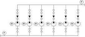
Figure 2 – flowsheet WILO-MPS
Application:
Automation System WILO-MPS [4] created by automation, pumps for water and heating systems with the number of pumps from 1 to 6 in the power range of pump motors from 1 to 630 kW, mains voltage of 380 V.
Recommended for automatic lifting and water circulation:
- – first lift stations, water intake and water intake sites (OVC)
- – Stations of the second, third, fourth, lifting
- – Booster Pump Station (PNS)
- – Water–pumping stations (VNS)
- – Network pumps and pumping group
- – Pumping stations and heat circulation
Table 1 Specifications
| type regulation station | Maintaining pressure, flow, or a difference of |
| Number pumps | 1 to 6 (more by special order) |
| Currents | from 3 A to 1120 A (more by special order) |
| Power | from 1 kW to 630 kW (more by special order) |
| Electricity according to GOST 13109-97 | 380 V ± 10%, 50Hz ± 0.2; |
| distortion factor synusoydalnosty | Kui less than 8.0; |
| fluctuation frequency range | +/- 5%; |
| degree of distortion operating voltage | = 3; |
| EMC requirements according to IEC 60947–1 – severity | 3; |
| ambient temperature | 0..+40 C |
| Degree of protection IP | 54 |
| type connecting analog sensors | 4–20 mA (passive) |
| type of connected sensors protect pump | thermistor PTC, PT 100, bimetal, 1 analog vibration sensor (4..20 mA), 1 discrete sensor added protection |
| type of connected digital signals | dry contact |
| type output digital signals control cabinet | dry contactmax 220 V, 5 A |
| maximum distance to the connected sensors | 200 m |
| intersection of wires connected to sensors | at least 0.75 mm² |
| Max. cable length from the control cabinet to the end of the power switching cabinets | 200 m |
| Max. length of the cable to the engine with the throttle output | 50 m shielded, 100 m Unshielded |
| Max. length of the cable to the engine with an output choke | 150 m shielded, 250 m Unshielded |
| Supported communication protocols | Industrial ethernet, Modbus, Lonworks, Industrial Ethernet c/ADSL, Modbus c/GPRS, Profibus |
| Installation of power and signal cables make different trays or in a tray with metal wall | |
4. Modeling node
control the water level in the tanks.
Calculation of regulatory body:
Equation water level in the tanks drives:
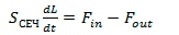
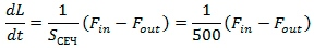
S_sech – cross-sectional area of the storage tank.
Calculation of the transfer function of the actuator:
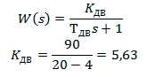
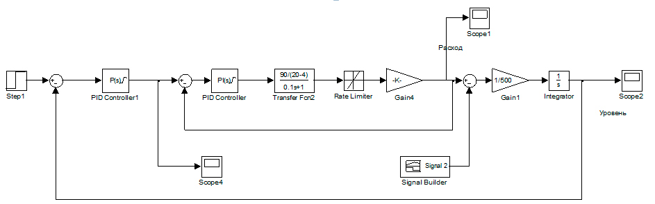
Figure 3 – Simulation model of the water level in the storage tank
When developing controller can use the technique of choosing parameters based on Möbius transformations [5].
simulation results are shown in Figure 4:
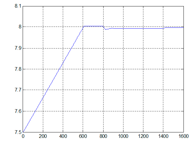
Figure 4 – The water level in the storage tank
Figure 4 shows that there is an error in the system of regulation, but it is in the margin of error.
control line pressure.
Drawingmathematical model pump:
According to the chosen modelpump [7], represent its characteristics:
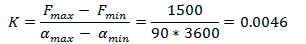
We are interested in the dependence of flow Q, [ m3/h] on the power N, [kW]. We represent this relationship as an array:
N = [270,300,310,380,400,450,510], kW
Q = [0,200,450,800,1000,1400,2000], m3/h
Table 2 - Parameters of the asynchronous motor AIR802A [8]
| Nomynalnaya POWER | Pn = 3*746 (BA), |
| deystvuyuschee lyneynoe tension | Un = 220 (B) |
| nomynalnayachastota | fn = 60 (Hz) |
| stator Resistance | Rs = 0.435 (Ohm) |
| stator inductance | Ls = 2.0e–3 (H) |
| Rotor Resistance | Rs = 0.86 (Ohm) |
| inductance Rotor | Ls = 2.0e–3 (H) |
| vzaymnaya inductance | 69.31–3 (H) |
| moment of inertia | J = 0.089 (kg*m^2) |
| Factor trenyya | F = 0 (N*m*c) |
| number of pairs of poles | p = 2 |
Figures 5 and 6 present the model in Simulink
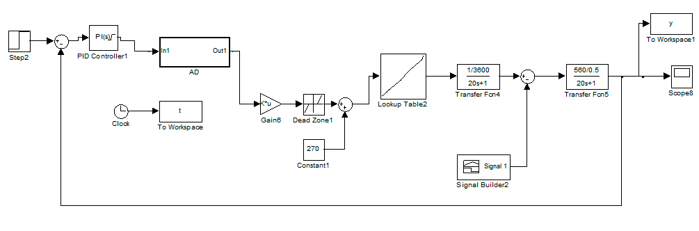
Figure 5 – Simulation model to maintain pressure in the general collector
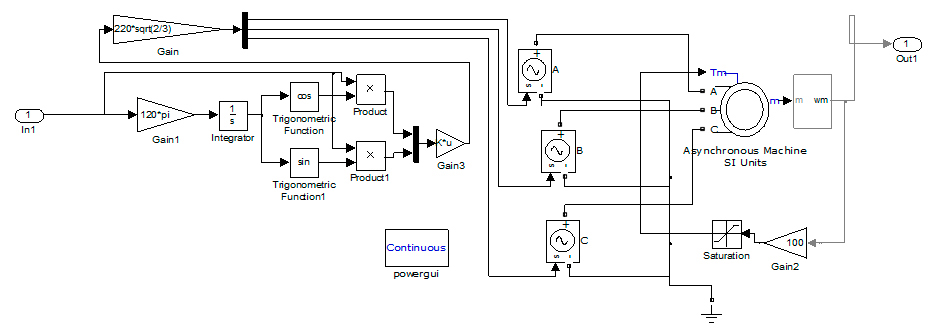
Figure 6 – A simulation model of the induction motor AIR80
simulation results presented in Figure 7:
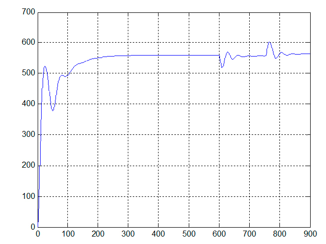
Figure 7 – Transient pressure
Under predetermined pressure value P = 560 kPa, it may be concluded that the system is modeled correctly.
Conclusions
was designed ACS process water [9]. ACS effectively solves the tasks assigned to it. ACS analysis showed that the developed system more efficient and cheaper to build, than the use of ready-made options from leading companies.
Following mathematical models were collected and modeled in an environment Matlab Simulink [10]:
- – a model for the water level in the tanks drives;
- – model maintain a constant pressure in the common header with unstable load.
were obtained and analyzed transients data models.
As a result of this project, you can examine in more detail the strengths and weaknesses of the resulting SPG for further improvement of the system, eliminate gaps and improve the efficiency of the system.
References
- Наказ Міністерства житлово-комунального господарства від 06.09.10 р. 316
Щодо розроблення схем оптимізації роботи централізованих систем водопостачання населених пунктів України
. - Наказ Міністерства ЖКГ від 23.12.10 р 476
Про затвердження Методичних рекомендацій з розроблення схем оптимізації роботи систем централізованого водопостачання та водовідведення
. - И. В. Кожинов Устранение потерь воды при эксплуатации систем водоснабжения/ И. В. Кожинов, Р. Г. Добровольский/ 2-е изд., перераб. и доп.-М: Стойиздат, 1988г. – 348 с.
- Сайт компании WILO-MPS: http://www.wilo-mps.ru/.
- Науковi працi Донецького Нацiонального технiчного унiверситету.
О выборе параметров преобразования Мебиуса при конструировании стабилизирующих регуляторов
, А. В. Хорхордин, С. С. Батыр, А. А. Безрук. - Автоматизация систем водоснабжения и водоотведения, А. А. Рульнов, К. Ю. Евстафьев, издательство:
Инфра-М
, 2010 г. – 208 с. - Электронный каталог насосов: http://www.uptc.ru/category/view/id/1.html.
- Автоматизация контроля параметров и диагностика асинхронных двигателей, О. Д. Гольдберг, И. М. Абдуллаев, А. Н. Абиев, издательство: Энергоатомиздат, 1991 г. – 160 с.
- Автоматизация систем водоснабжения и водоотведения, Г. С. Попкович, М. А. Гордеев, издательство:
Высшая школа
, 1986 г. – 392 с. - Моделирование процессов и систем в MATLAB, Ю. Лазарев, издательская группа BHV, 2005. – 512 с.
