
Compressors are a group of mechanisms have been widely used in all industrial enterprises.
Compressors used for compressed air or other gas pressure of over 4·105 Pa in order to use its energy drives pneumatic hammers and presses, air tools, pneumatic devices, producing gaseous oxygen, etc.
For example, in the manufacture of iron and steel (converter production of steel, electric furnace production and oxygen blast in blast furnaces) is widely used compressed oxygen, which is obtained by using an air separation unit (ASU). It includes facilities for compressing and purifying the air, cooling it down to cryogenic temperatures, separation by distillation, heating the resulting products, and their pumping compression of [1].
Schedule of compressed air consumption in industry, as a rule, has a variable character within days. For proper operation, it is necessary to consumers that the air pressure is kept constant - it is one of the main requirements in the automation of compressor installations. Airway pressure in the network depends on the air consumption and performance of the compressor. When the air flow capacity of the compressor is equal to the pressure in the network will be nominal. If the intake air is becoming more performance, the pressure decreases and vice versa [2].
Currently adjustment of throttling provided by the turbocharger, which narrows the range of regulating the pressure is economically disadvantageous, and [3, 4]. In this regard, it is urgent that improve the efficiency of the turbocharger through the introduction of an automatic frequency control of the drive motor.
Centrifugal compressor, dynamic action (Fig. 1), the air enters through the inlet control valve built and enters the first stage of compression, where the impeller (1) lends an air of a certain speed. The air then passes through a diffuser (2), where the velocity is converted into pressure. Integrated air intercooler (3) removes heat of compression increases and thereby the efficiency. The air passes through the moisture separator (4) made of stainless steel in the low speed zone where the condensate is separated. When changing the direction of air flow 180°, before entering the subsequent stage, moisture transport ceases. Such technological sequence is conserved in all subsequent stages up until the compressor will not develop the desired working pressure.

Figure 1 - The design of a centrifugal compressor
(animation: 5 frames, 5 cycles of repeating, 164 kilobytes)
Modern compressors as the drive are asynchronous and synchronous motors whose speed is not adjustable. The largest application for compressor drive received asynchronous motors with squirrel-cage rotor.
Controlling the flow rate and pressure of the compressed gas in a centrifugal compressor machine in the following ways:
The level automation system should allow real-time to accurately determine the operating point coordinates relative to the compressor surge limit line and implement effective surge control, taking into account the dynamics of the operating point closer to the surging boundary (Fig. 2).

Figure 2 - Polytropic pressure - flow rate [5]
Ability to calculate in real time to minimize the required adjustment margin (distance from the boundary line to the surge control), i.e. maximize the area available operating points without opening the compressor bypass valve, while providing a high efficiency compressor system without compromising security [5].
Antisurge protection system are performed on two-loop. The first circuit carries surge control and prevents dangerous approach to the operating point of the compressor surging boundary due to bypass gas through the bypass valve in the discharge line of the suction line. While continuously calculates the relative distance from the operating point of the compressor to the surge limit, taking into account changes in dynamic parameters on the suction and discharge conditions, including changes in the composition komprimiruemogo gas. If the compressor has several sections polytropic compression, calculated the relative distance from the operating point to the surge limit of the compressor each section separately and regulation occurs in the parameters section, the operating point which is closest to the surging boundary.
The second circuit is open-antisurge protection and performs a forced opening of the bypass valve when the signs of surging . The algorithm is triggered by the forced opening team Signalling surge. Warning surging group produces statistical signal processing mode parameters of the compressor in order to detect signs of surging . For surging detecting signals commonly used pressure discharge current main motor and differential pressure flow meter device. These signals are processed in real time with a period of 10 ms at the same time in four surging detecting algorithms. Application of the group of statistical signal processing allows full use of mathematical methods of information processing and pattern recognition, which allows you to diagnose the phenomenon of rotating stall and surge with a minimum of false positives signaling even very noisy source signals, that is, to achieve the optimal balance between sensitivity and noise immunity.
Full time information processing and issuing of control in the control loop bypass (relief) valve is 40 ms. This allows efficient use of modern high-speed anti-surge valves eventually fully open 1.5–2 [6].
Compressor units are very energy-intensive facilities. Consequently, the effective use of compressed air and reduce the cost of its production is of great importance. The successful solution of this problem depends largely on the activities related not only to the improvement of compressor units, as well as the improvement of the pneumosupply, which refers to the reduction (2–3 times) compressed air leaks, introduction of accounting, regulation and supervisory control and pressure air consumption.
All materials used in industry control systems are automated and based largely on the principle of throttling the compressor inlet air. Among the existing management system to allocate:
Security Subsystem and compressor control consists of two main parts:
For workplace organization machinist operator uses the local station PanelView industrial version of the cabinet installation or, in the case of a compressor station automation, the workplace is organized based on industrial PC performance software RSView SE.
The main controller is a hardware-based ControlLogix5555 designed to perform the following basic functions:
survivalat failure of field instrumentation, either individual measurement channels;
Surge control algorithm parameters are incorporated in the main controller, resistant to changes in the composition komprimiruemogo gas and consider the dynamics of the operating point closer to the surging boundary.
The disadvantages of such a technical decision is low due to the use energoeffektivnost throttling.

Figure 3 – Automation System centrifugal compressors for explosive plants and facilities
Unified set of office automation mine compressor stations UKAS type intended for automatic control of mining compressor stations equipped with reciprocating and centrifugal compressors (Fig. 4).

Figure 4 - Block diagram of automatic control of compressor station equipment using UKAS
In the apparatus taken into account the use of compressor drives with thyristor or brushless excitation system, the use of sealed relay contact and contactless logic elements and application of variable speed drive compressor units. The composition includes UKAS:
1 - node issue commands and addresses of the program;
2 - dial-distributor program of work stations;
3 - control and regulation units respectively 1st and n-m;
4 - air pressure regulator in the pipeline;
5 - sensor heat control;
6 - the first and n-th units, respectively;
7 - main line of compressed air; VEP1-VEPn - anti-surge protection regulators the first and n-th compressor units, respectively.
Control and regulation unit provides command processing setpoint distributor, technological protection and capacity control of the compressor unit.
The kit includes:
All equipment is mounted in a closets.
The disadvantage of this apparatus is the lack of modern management system, which entails a poor energy efficiency.
Centrifugal compressor control system Centac firm is based on a microprocessor unit, the so-called panel SMS. It performs all the functions of management and monitoring, and control of the auxiliary control equipment, such as the main motor starter, oil heater and pre-lube pump. CMC panel equipped with tailor made computer board called basic control module (BCM). This motherboard is equipped with a microcontroller and memory chips, which determine the actions panel for various combinations of measured pressure, temperature and vibration. All the technical means for data analysis, the number of input channels and output (I / O) and memory system are optimally matched for precise control and protection of compressors Centac.
System Specifications CMC:
To control the compressed air system management methodology CMC uses operating parameters and impulse control.
Management of operating parameters. CMC has three standard operating modes operating parameters or methods of operation. This is a) Unloading, b) Modulation and c) Automatic dual control model for an air compressor, operating under constant pressure. To clarify the following discussion, Figure 5 is a diagram of a compressed air system and communication with the compressor compressed air system of the enterprise.

Figure 5 - Coupling scheme compressor compressed air system company
The disadvantage of this control system is control by throttling.
The aim is to increase energy efficiency turbo-compressor installation
The main objectives of the study:
Manage performance of centrifugal compressors by varying the speed of the drive motor
provides significant improvements in energy efficiency of the system electric drive - compressor.
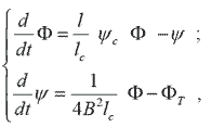
To describe the dynamics of the compressor model is used Moore – Greitzer[7, 8, 9]:
|
(1) |
where Φ – air flow through the compressor; ψc(Φ) – gasdynamic characteristics of the compressor; ψ – the degree of compression of the air flow compressor; Β – Greitzer parameter; lc = lвх + lк + lвых; lвх – the length of the suction pipe; lк – the length of the compressor; lвых – the length of the pipe on the compressor discharge; ΦΤ – flow network; t=Uτ/R - the relative time, where U – tangential velocity average diameter, R – the mean radius of the compressor, t – real time.
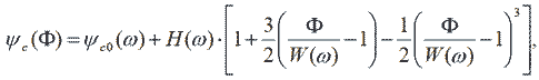
It is envisaged that the compressor with a uniform circumferential flow has characteristic ψc(Φ) according to a cubic:
|
(2) |
where ψc0(ω)=Kkω2 – in the absence of compression rate; W = kwω – half-width of the gas-dynamic characteristics; H = kHω2 – half-height of the gas-dynamic characteristics; Kk, kH, kw – structural factors of the compressor; ω – rotational speed of the compressor.
In equations (1), (2) a criterion B, Greitzer proposed [9], takes into account the speed of the compressor rotor. For values B > Bкр surge occurs in the case of B < Bкр - negotiable breakdown and Bкр - critical value Greitzer.
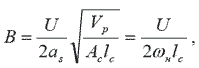
Parameter B is determined from the expression:
|
(3) |
where as – the speed of sound; Vp – volume of the receiver; Ac – the area of the pipeline compressor; ωн – the rated speed of the compressor rotor.
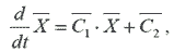
Combining equations (1) and (2) in the matrix differential equation:
|
(4) |
where 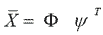 - vector of state variables;
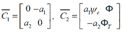 - matrix coefficients;
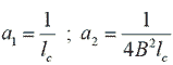 .
.
Structural diagram of a computer model, corresponding to equation (4) is shown in Figure 6.
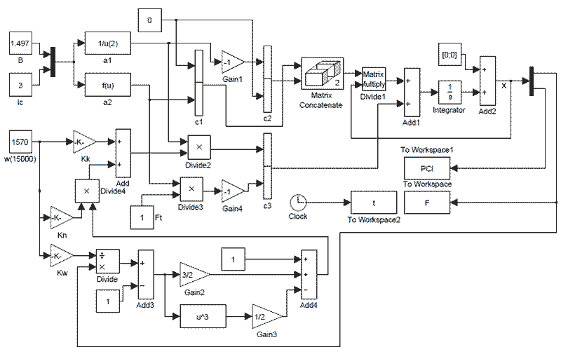
Figure 6 - Block diagram of the model of a centrifugal compressor
Consider starting a compressor unit for the following parameters: Vp = 1.5 m2; H = 0.18 Pa; W = 0.25 kg/s; Aс = 0.01 m2; as = 340 m/s; Lc = 3 m; ψc0(ω) = 0.3 p.u.; B = 1.497 p.u.; R = 0.1 m; lвх = 1 m; lвых = 2 m; U = 114 m/s; ω = 3000 rad/s; ΦТ = 0.5 m3/min.
Graphics state variables when the compressor starts, the resulting simulations are shown in Figure 7.
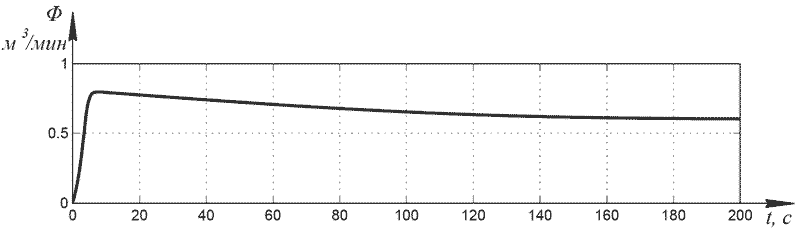
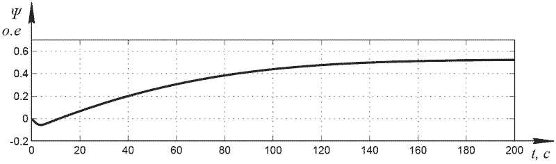
Figure 7 - Graphs state variables obtained by modeling:
а – air flow through the compressor, б – degree of compression of the air flow
Thus a reasonable mathematical model of a centrifugal compressor in the form of matrix differential equation can be used for modeling compressor system with frequency-controlled electric drive.
Structure turbocharger with automatic frequency control motor, presupposes (Fig. 8) pressure sensors in the supply network 1 and the output of the compressor motor temperature sensors 3, 4 bearings and oil 5, the oil level sensor 6, 7 oil pressure and motor speed 8 .

Figure 8 - Block diagram of the automation system compressor unit
The actual air pressure in the pneumatic system is measured by a pressure sensor at the outlet of the compressor, which receives a signal to the control unit, where a comparison with the set point. When an error signal, the control unit instructs the inverter, which in turn generates a signal to increase or decrease the speed of the drive motor of the turbocharger. During the operation of the plant is continuously removed and analyzed the temperature sensor motor, bearings and oil temperature. Oil pump work, during work carried out by the turbocharger oil pressure measurements at the pump outlet. By lowering the oil pressure or level in the oil below the set, the control unit stops the compressor and an alarm. During start-up information from the compressor oil level sensor, oil pressure and temperature enters the module, where a signal is generated and analyzed for inclusion of the main compressor motor .
The main element of the device is a microcontroller, which is designed for processing information from the sensors and controls the logical decision- making and timely generating a control signal to the frequency controller. Signals to the microcontroller through a matching unit receives an input signal, which converts signals, galvanic isolation link devices with contact sensors and controls. Block matching output signal is intended for converting the output signals of the microcontroller in the control apparatus starting and oil pump drive motor valves. To transfer information between your device and a computer operator compressor station device includes an adapter data RS-485 interface.
The studies were obtained transients start the turbo-compressor installation. Variable speed induction motor using a frequency converter, allows not only to reduce the loss and saves energy by 20% to 40%, and continuously adjusting the rotational speed of the motor from a nominal value to a minimum value while maintaining the maximum torque on the shaft. Application of the inverter will increase the life and increase the reliability of the drive and equipment and improve the efficiency of oxygen production by strong pressure on the network.
Created a computer model to simulate the operation of the system allows control of the turbo compressor unit. Variable speed control over a wide range with storage sufficient rigidity characteristics is possible only when frequency control, which gave a significant reduction of accidents and network installation itself.
In writing this essay master's work is not yet complete and therefore the information in this essay, is not complete. Final completion: December 2014.