
Abstract
Contents
- Introduction
- 1. Actuality
- 2. Purpose and research problems, expected results
- 3. Review of research and development
- 3.1 Laser Sensor rf620
- 3.2 Automated diagnostic system for the control of geometric parameters of wheel pairs cars
COMPLEX
- 3.3 The system of automated control wheelsets
AURA
- 4. Choice of method
- Sources list
Introduction
Railways are widespread and offer many advantages – high capacity, reliability, comparatively high speed. There are variety of loads transported by rail (especially mass: raw materials, agricultural products). You should not forget that the railway transports not only raw materials to manufacturers and products to consumers but it is also a transport for many people, for small (suburban railways) and over long distances. Also lots of people daily use the tram and subway.
Trains are not just a part of the past that have not sunk into oblivion. On the contrary, they are the part of developing transport. First in Japan, and now in Europe a system of high-speed railways, admitting at speeds about 300 miles per hour. The electrified railways (currently they are the most railways with heavy traffic) are much more environmentally friendly than road transport.
These and many other factors suggest that rail transport is widespread and most likely will not lose their positions soon, and perhaps will strengthen them. So it is very acute question of the safety use of trains. In my work will be conducted researches of the system that scan the surface of a railway wheel.
1. Actuality
The slightest deviations of the parameters of railway wheels from nominal lead to reduced running and dynamic characteristics of locomotives and wagons, and therefore safety operation compositions. In this regard, in the manufacturing process, as well as exploitation of railway rolling stock for railway wheels are put very high demands on the control and conservation of geometrical parameters.
Until recently, the measurement of the wheels and the calculation of their rejection were in using the contact devices (mainly templates). Patterns measured profile and riding the crest thickness. Hogging measurement is usually carried out control plate or template type spider.
NDT inspector applies the pattern to the wheel, and then using the probe determines the maximum gap. The measurement result is highly dependent of the skill level of NDT inspector, the correctness of using the templates, probes, etc. Naturally that person makes some errors in the measurement.
The principle of applying patterns has a lot of shortcomings. For example, if the wheels begin to eat through one procedure (for example, sloping ridge instead of GOST 9036-88), then there is a problem of quality control bore because the old patterns are not suitable for this task, you need to make new ones.
Wheel weight is 500 kg. In determining the axial hogging wheel is placed on the control plate, and then determines the gap between the plate and the wheel throughout. This mechanism inevitably leads to roughness on the control plate, and therefore the measurement result depends on the plate on which they are held.
We should not forget such an important factor as time. At observance with all requirements of GOST for complete measuring wheel by contact methods by skilled NDT inspector it takes about 20 minutes, which significantly slows down the entire process.
About 30 geometrical parameters of railway wheels must be monitored during operation and measurement. Most of them need to be measured with high accuracy (maximum axial warping should not exceed 0,1 mm). Using templates to implement such kind of task is difficult, and definitely takes a relatively large amount of time. In this regard, the need to create high-quality systems that could provide the required accuracy.
Disadvantages of contact measurement method:
- the duration and complexity of the measurement process;
- the dependence of results of measurements of the
human factor
; - the dependence of results of measurements of the deformation of contact devices in during operations;
- impossibility to reconfigure contact devices in accordance with changes to the requirements of the final product.
Rid of these shortcomings can be using contactless methods of control. As a means of measurement, you can use laser sensors-rangefinders (eg, raster rangefinders). Sensors of this kind in a single scan works with full profile (and not with a single point). Length of surface scanning is range (depending on the laser power and the error of measurement).
2. Purpose and research problems, expected results
Objective:
provide metrological and geometric characteristics of the workpieces of railway wheels using optical method geometry control and compensation of dynamic disturbances environment that affect the measurement results, as well as improving metrological reliability and reduced consumption of materials and energy-consuming for further processing billet wheels.
To achieve the goal we need to solve the following problems:
- Development of spectral interaction of optical rangefinder and workpieces of heat wheels.
- Design techniques installation of the optical components relative to the workpiece during the rolling.
- Analysis of disturbing factors and their influence on the measurement result.
- Formation of ratings of metrological parameters and characteristics of the device.
- Development of primary algorithm for reconstructing workpiece geometry wheel.
- Synthesis of structural scheme of matching the system of speed of wheel rolling condition.
3. Review of research and development
3.1 Laser Sensor rf620
Have a measuring range on the X axis 150 mm (Fig. 1). By such adjustment sensors capture range of 100 to 350 mm. The smaller the measurement range of the device – the higher the accuracy. The scanning speed of such sensors is very high – around 100 scans per second. Per scan sensor can get up to 1024 points.
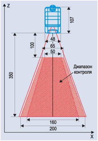
Figure 1 – Measuring range raster laser sensor RF 620
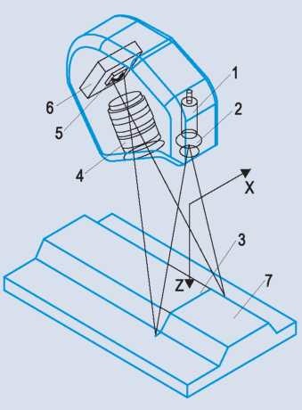
Figure 2 – The principle of the raster scanner-EDM
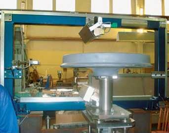
Figure 3 – General view of the complex
The basis of the raster scanner-range finders on the principle of optical triangulation (Fig. 2).
Semiconductor laser 1 is formed by a lens 2 in the form of lines 3 and is projected onto the object 7. Radiation reflected by the object lens 4 is going on a two-dimensional CMOS-matrix 5. Resulting image object contour analyzed by a signal processor 6, which calculates the distance to the object (axis Z) for each of the plurality of points along the laser line on the object (X coordinate).
It is based on the use of raster laser sensors. The setup was designed to avoid the difficulty in controlling all described above.
The mechanical part of the complex was extremely simplified, which significantly improve the reliability and durability of the equipment [6].
3.2 Automated diagnostic system for the control of geometric parameters of wheel pairs cars COMPLEX
Purpose: To identify the moving train wears solid wheels. Information obtained to the nearest service location (PTI).
Principle of the system is based on non-contact laser control geometry moving three-dimensional objects using triangulation position sensors.
Features: non-contact measurement of geometrical parameters wheelsets rolling on a moving train at speeds up to 60 km / h in different climatic conditions.
Application of the system can increase the reliability and operation of rolling stock as possible to eliminate the probability of accidents on the railway caused by defects wheelsets [1].
3.3 The system of automated control wheelsets AURA
The unit is designed for mechanized and automated inspection of wheels bulging wheel pairs (CP) for different types of longitudinal, transverse and defects in the bulk.
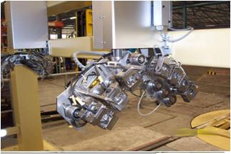
Figure 4 – View of the complex control wheelsets AURA
Design and function
Installing mainly consists of three parts: the stand rotation KP portal and placed on it scanners wheels. All parts are interrelated oboj by the central control system (PLC).
In an ultrasonic flaw detector used MODUS 03, and as eddy – Elotest Ms / IC. To determine the coordinates of defects from the bench rotation gearbox via Profibus in flaw is coming from the wheel angle sensor.
Flaw have computers and can perform the task of controlling autonomous and independent. NDT works for the host computer, which controls both the flaw and stand management system (PLC). In managing computer program is selected (volume) control, using the host PC is being process control inspection, here saved the test results are presented and processing and visualization. In complete control of the data stored in the database and printed reports.
Data Bank is a multi access system so that a normal operator can not change/adjust the test results. A copy of the data bank is reserved for DVD-ROM. Maybe a bunch of optional installation of a data bank with the data bank depot road [4].
4. Choice of method
From the examples it can be concluded development that when used as an optical sensor device, we obtain faster scanning time which is a very important factor. It should also be noted that the optical sensors provide the required accuracy when solving this problem. Since the production rate plays a very important role, for the solution of the problem it was decided to use that optical method.
This master's work is not completed yet. Final completion: December 2015. The full text of the work and materials on the topic can be obtained from the author or his head after this date.
Sources list
- Компелкс [Электронный ресурс]. – Режим доступа: http://www.labracon.ru/ru/products/complex
- Дефектоскопия деталей подвижного состава железных дорог и метрополитенов / [ Ильин В. А., Кожевников Г. И., Левыкин Ф. В., Штремер Ю. Н.]; Под ред. Ильина В. А., М. Транспорт 198. – 318 стр.
- Мойкин Д. А. Неразрушающий контроль в вагонном хозяйстве. Учебное пособие, Петербургский Государственный Университет путей сообщения, Санкт-Петербург, 2001. – 87 стр.
- Компания ООО «Матириалз Лаб» [Электронный ресурс]. – Режим доступа: http://www.materials-lab.com.ua/...
- Андреев А. Н., Шерешев А. Б. Оптические измерения: Учебное пособие по курсу «Оптические измерения». М.,:Изд. МИИГАиК, 2002 г. –72 стр.
- Дефектоскопист.ру [Электронный ресурс]. – Режим доступа: http://defektoskopist.ru/showthread.php?t=606
- Справочник конструктора-машиностроителя. Анурьев В. И. Издательство «Машиностроение», 2001 год. – 920 стр.