
Content
- Introduction
- 1. Relevance of the topic
- 2. Research goals and objectives, expected results
- 3. Review and analysis of known solutions automation object
- 4. Heat exchanger as a control object
- 5. Analysis of the dynamics ACS heat exchanger
- Conclusion
- References
Introduction
Heat exchangers are an integral part of most manufacturing processes, so the task automation counterflow heat exchangers is very important due to the significant energy consumption of heat exchangers and their prevalence in industrial practice.
In the current regulatory counterflow heat exchanger does not solve the problem of optimal heat transfer under varying loads. Thus, as a rule, limited to the task of stabilizing the temperature of one of the output streams. Thus, the task of modernizing the existing control system heat exchangers, maintenance of optimal conditions in the dynamics of heat transfer is very important.
1. Relevance of the topic
Processes of heat transfer through the heat exchangers from one fluid to another are very widely used in industry and the public sector, the household sector. Often we just use the result of heat, without attaching any importance to it, without seeing the process.
Shell and tube heat exchangers are the most common devices. They are used to heat and thermochemical processes between different liquids, vapors and gases - as unchanged, and changes in their physical state.
An important step in improving the management system under consideration is subject to analysis of the heat exchanger as a control object, ie Identify all significant input, output and disturbing variables.
2. Research goals and objectives, expected results
Objective: To improve the quality control process automation system heat exchanger due to the review of the prior art control heat exchangers, as well as its analysis as a control object.
Task master's work:
- Investigate counterflow heat exchanger as an object of automatic control.
- Improving the quality control process temperature process stream at the outlet of the heat exchanger under the action of disturbances due to the modernization of automatic control countercurrent heat exchanger.
- Modeling process temperature control process flow at the outlet of the heat exchanger under the action of disturbances and quality control analysis of heat exchanger.
3. Review and analysis of known solutions automation object
There are several variants of known automation solutions exchanger. Consider four of them [1].
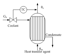
Figure 1 – Diagram of single- closed ACP fluid temperature in the vapor-liquid heat exchanger
Option 1. Single-loop closed ACP (Fig. 1) using a PI or PID temperature control ensures no static error, but at strong perturbations on fuel or fluid temperature transient quality may be unsatisfactory.
Option 2. Introduction dynamic feedforward compensation G or θin is impractical, since the theoretical compensators with transfer functions
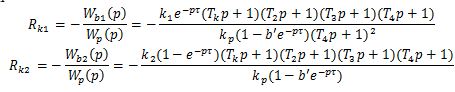
physically unrealizable, and the use of approximate compensators may be ineffective. Therefore, in practice, limited to static compensation of these disturbances. Examples of such systems is a cascade ACP cost ratio Gn/G with correction for θout (Fig. 2).
Option 3. Cascade temperature control system (or pressure) in the annulus corrected assignments θout (Fig. 3) will be effective for strong perturbations in pressure or temperature of the heating steam. The temperature (or pressure) in the casing in this case plays a role of an intermediate position, which responds faster to these perturbations than the outlet temperature of the fluid [3].
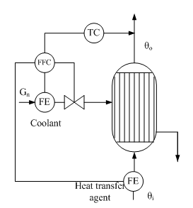
Figure 2 - Cascade ACP temperature liquid to a vapor-liquid heat exchanger (with ratio control costs in the inner loop)
Option 4. If you want high quality control, it is advisable to apply the scheme to bypassing the process flow around the heat exchanger and then mixing hot and cold streams. In this case, there is an additional control action - flow distribution G1 and G2. Fig. 5 shows an example of such a heat exchanger system automation . Temperature controller 1 has a supporting role - stabilization of the temperature θ ", The main task - to regulate fluid temperature after mixing - the responsibility of the regulator 2 . In this system, the quality of regulation θout determined by the dynamics of the second circuit, in which the object is almost inertial unit, since a small volume of the mixing chamber of the mixing process time constant substantially equal to zero.
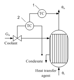
Figure 3 - Functional diagram of the cascade ACP temperature liquid to a vapor-liquid temploobmennike (with a temperature condensate in inner loop): 1 - liquid temperature control, 2 - control the condensing temperature in the housing
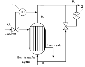
Figure 4 - The temperature control fluid in the circuit bypassing the flow around a heat exchanger 1 - temperature control fluid outlet of the heat exchanger; 2 - temperature control fluid after mixing
In this paper we will use the second version of the automation system with the addition of heat exchanger control the coolant temperature at the outlet.
4. Heat exchanger as a control object
Consider the use of a heat exchanger to produce sulfuric acid by wet catalysis. Method wet catalysis is one of the main methods of obtaining sulfuric acid from hydrogen sulfide and consists of three stages: the burning of hydrogen sulfide oxidation of sulfur dioxide, which is formed on the catalyst, and the condensation of sulfuric acid. It is now widely used scheme of sulfuric acid proposed Haldor Topsoe A/S, shown in Fig. 5.
Figure 5 - Scheme of production of sulfuric acid from hydrogen sulfide: 1 - sulfide, 2 - furnace 3 - HRSG 4 - combustion air, 5 - a steam system, 6 - superheated air, 7 - pole machine, 8 - blower 9 - acid gas cooler, 10 - in the purge gas pipe, 11 - capacitor 12 - pump acid, 13 - cooler acid, 14 - acid 15 - air
(animation: volume - 149 KB; size - 575h335; number of frames - 5, the delay between shots - 0.5 with the number of cycles of repetition - 5)
When cleaning combustion gases are usually obtained concentrated hydrogen sulfide gas (90%), so the furnace where it is burned, a large amount of heat. In this connection, the combustion furnace is introduced into a large excess of air therein, or a recovery boiler coils. In step combustion of hydrogen sulphide, sulfur dioxide obtain [6].
Gas from the furnace at a temperature of about 1000 °C is supplied to the recovery boiler, where the heat of gas used to generate steam. The cooled gas at a temperature of 400-420 °C is supplied to the relay apparatus. Due to the fact that the exothermic process in the apparatus, the gas is cooled between the layers in order to shift the equilibrium in the desired direction. After conversion stage gas is cooled to a temperature below 300 °C, the water vapor reacts with the gas to form sulfuric acid (sour gas).
After cooling the acid gas, gaseous sulfuric acid enters the shell and tube condenser counter - exchanger (Fig. 6). The heat exchanger is positioned vertically with the body pipes falling film of acid-resistant borosilicate safety glass [7].
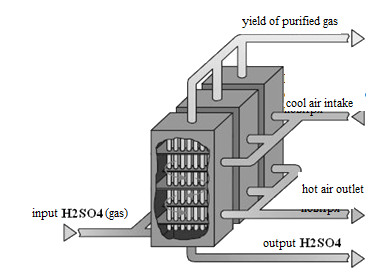
Figure 6 - Type tube heat exchanger
Process gas passes through the inside of pipes, cooled by outside ambient air, so there is a high supersaturation of the sulfuric acid vapors. Sulfuric acid is condensed in the tubes flows down and is collected at the bottom of the condenser. Ready-transparent and has an acid concentration of ~98%. Cleaned gas exits the condenser at a temperature of about 90-110 °C and is sent directly to the pipe.
Part of the original hot air is used for combustion in the furnace organization, and the rest can be displayed in the tube to increase the lifting power or gas can be used to preheat boiler feed water.
Topsoe process feature consists in that at its implementation does not form sulfuric acid mist so there is no need to install a heat exchanger after tumanoogranichitelya.
Thus, according to the real work, all the essential factors affecting the heat exchange process, broken down into the following groups [2]:
- Controlled perturbations - those perturbations that can be measured, but it is impossible or unacceptable to stabilize (fuel power supplied directly from the previous device, ambient temperature, etc. For the process such perturbations are Tinh coolant temperature, and the temperature and flow rate of the heated Tinc, Gc at the unit inlet.
- Uncontrolled perturbations - perturbations that are impossible or impractical to measure directly. First - this drop in catalyst activity change in the coefficients of heat and mass transfer, etc. As an uncontrollable perturbation in the subject may act scale, formed on the surface inside the heat exchanger tubes, and the vapor pressure of participating in heat transfer.
- Output variables. One of them is selected adjustable coordinates. In constructing the closed systems of regulation as controlled coordinates selected technological parameters, which means that the change inappropriate material or heat balance in the machine. These include: temperature and heat transfer Touth Touth.
- Control variables - input signals control object that can be used to influence the operation of the object: the flow rate of coolant Gh.
Figure 7 shows a block diagram of the surface heat exchanger.
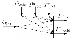
Figure 7 - Scheme of relationships between variables in a heat exchange unit
5. Analysis of the dynamics ACS heat exchanger
Regulation of surface counterflow heat exchanger is to maintain a constant temperature of the coolant at the outlet of the heat exchanger, e.g., Tx2 [4].
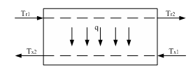
Figure 8 - Block diagram of the countercurrent heat exchanger surface
Tx2 temperature depends on the rate of heat transfer or heat flux q through the wall; in turn, this temperature is determined by the driving force of the process or medium temperature pressure Δ Taver [8].
To conduct initial data modeling ask ourselves:
F=282 m2 - exchanger surface
ν1=ν2=4400 m3/h
c1=c2=0,33 m3*grad - specific heat environments
α1=α2=12 m2*h*grad - heat transfer coefficient
G=5400 kg - weight of heat exchanger tubes
сs=0,115 kg*grad - specific heat exchange surface under steady state conditions
Т1n=470 °С - temperature of the primary coolant
Т2н=50 °С - temperature of the secondary coolant
Given the above mathematical model for this problem takes the form:
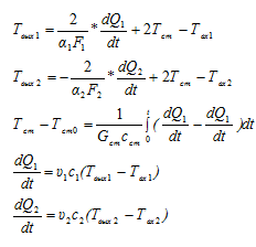
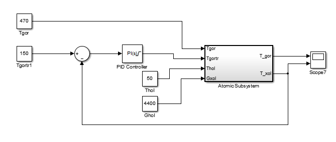
Figure 9 - Modeling scheme ACS
Based on this mathematical model, we construct the circuit simulation of the heat exchanger:
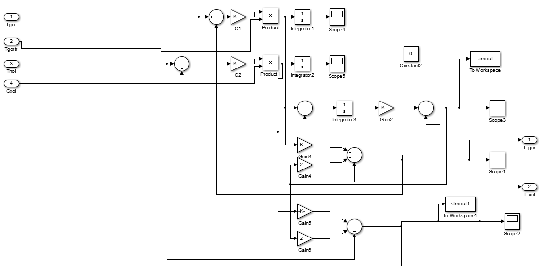
Figure 10 - Scheme of modeling countercurrent heat exchanger
To regulate the desired temperature at the outlet of the heat exchanger will modify the hot coolant flow through an automatically tuned PI controller [6].
As a result, we obtain the following simulation transients:
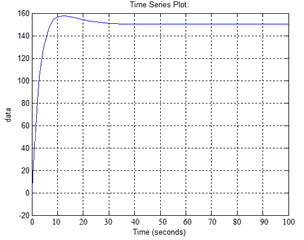
Figure 11 - Transient Response hot coolant at the outlet of the heat exchanger
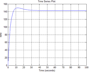
Figure 12 - Transient response of cold coolant at the outlet of the heat exchanger
As we see the transient response obtained have good quality control system: the overshoot of about 5%, the transition process about 15 seconds.
Conclusion
- Identify the essential factors affecting the process of automation.
- Analysis of the heat exchanger as a control object showed that the investigated object automation is complex, multidimensional and multiply the object of control , which is not taken into account the existing systems of automatic control.
- Based on the mathematical model and the simulations performed, the automatic control system installed heat exchanger , the heat exchanger that this model has a good quality control when properly tuned PI controller.
When writing this abstract of qualifying work is not yet completed a Masters . Date of final completion: December 2014. Full text of the work and materials on the subject of the work can be obtained from the author or his supervisor after that date.
References
- Dudnikov E.G. Automatic control in the chemical industry /E.G. Dudnikov, A.V. Kazakov, N. Sofieva, A.E. Sofiev, A.M. Tsirlin - Moscow: Khimiya, 1987. - 368.
- Lapshenkov G.I. Automation of production processes in the chemical industry / G.I. Lapshenkov, L.M. Polotsk - Moscow: Khimiya, 1982. - 377 p.
- Joffe I.L. Designing processes and devices of chemical technology /I.L. Joffe - L.: Chemistry, 1991. - 352.
- Automation of technological processes and production: a tutorial. Edited N.V.Kuzmenko. - Angarsk, 2005.
- Chernyshev N.N. Mathematical description of the heat transfer process in the countercurrent heat exchangers / N.N. Chernyshev, V.V. Turupalov, A.A. Pryadko / / Naukovі pratsі of Donetsk natsіonalnogo tehnіchnogo unіversitetu. Ser. obchislyuvalna tehnіka that avtomatizatsіya, Preview Issue 21 (183). - Donetsk: Donetsk National Technical University. - 2011, pp. 55-60.
- Chernyshev N.N. Setting temperature controls gases in the automatic control system of sulfuric acid / N.N. Chernyshev / / Collection of scientific works in Іnstitutu problems modelyuvannya energetitsі I.M. G.Є. Pukhov goal. Ed. V.F.Єvdokimov. - Kiev: Іnstitut problems in modelyuvannya energetitsі IM. G.Є. Pukhov, 2012. - Preview Issue 65. - S. 101-107.
- Planovsky A.N. Processes and devices of chemical technologies / A.N. Planovsky - Khimiya, 1962. - 362.
- Mankovsky O.N. Heat exchange equipment of chemical plants / O. Mankovsky - Leningrad: Khimiya, 1976. - 348.