Abstract
Сontent
- Introduction
- 1. Topicality
- 2.Research goals and objectives
- 3. Main objectives of the study
- 3.1 Analysis of the conveyor transport as an automation object.
- 3.2 Critical review of the prior art process automation conveyor transport.
- 3.3 Rationale and development of automation systems branched conveyor line.
- Findings
- List of sources
Introduction
The main means of delivering cargo to the modern mining operations is the conveyor transport. Conveyors (ЛК) to effectively replace the locomotive and cable revert due their advantages such as continuity, opportunities for automation, the ability to transport cargo in inclined workings, easy to build and branching lines, relative safety.
Its main advantages are: efficiency, high performance, due to the continuity of the process of transportation; reliability (availability factor reaches 0,999 for belt conveyors, for plate-0.987); technological devices to work with the automatic control system and therefore low labour services (1-4 pers. night shift on a single pipeline); the ability to transport cargo both on horizontal and the inclined mine workings; simplicity and ease of interfacing with equipment cleaning and preparatory faces.
1. Topicality
Master's thesis is devoted to the actual currently in Ukrainian mines problem of increasing the reliability of conveyor transport. By reducing the load on the drive belt. High load caused by high non-uniformity of cargo flows entering the transport installations, as assembly line for its technological purpose is the transport facilities serving stop. Technological pause shearer, including emergency stop lava, and periodic changes in their speed of movement along the stop cause unevenness or lack of traffic that would also affect the loading conveyor. At the same time characterized by a considerable underutilisation of trunk pipelines; continuous operation at idle. This negatively affects the technical and economic indicators means of transportation, as they are most of the time their work have a significant (2-4 times) underutilization lead to increased unit costs of electricity.
Currently in the coal mines to increase the efficiency of conveyor transport used coal accumulating bins and offers speed control conveyor belt with variable frequency drive (VFD). Striving to improve the reliability and reduce the cost of LC resulted in the widespread use of these unregulated drive based on asynchronous motors with squirrel-cage rotor (BP). However, as the analysis of the factors determining the mode LC, fixed drive is not sufficiently effective. One of the most important parameters affecting the reliability and efficiency of the conveyor system is the belt speed. Regulation of this parameter can be achieved by using special drive and cruise control [1].
2. Research goals and objectives, expected results
The aim of the research and development of the automatic control and stabilization of the electric load of coal mine conveyor belt. Automation object is a branched conveyor line.
3. Main objectives of the study
3.1 Analysis of the conveyor transport as an automation object.
Mine conveyor transport process-this process moving rock mass, materials, and in some cases, people using conveyors in mine workings. The mines for conveyor transport mainly used belt conveyors. Belt conveyor-conveyor device with continuous combined load-bearing and drive elements in the form of a closed flexible tape. Belt is driven by the force of friction between it and the drive drum; based on the entire length of the stationary roller carriages. To move cargo over long distances used conveyor lines, consisting of two or more conveyors.
Modern underground conveyor lines are characterized by a significant length (tens of kilometres) and branching highways, paced its parameters: length, topology, etc. In conditions of mines conveyor line can not be branched and branched. Under the straight-line conveyor line understand the single-threaded, in which the load on each conveyor comes from only one of the preceding pipeline and under branched-multi threaded line consisting of branches and part of the team. For branched conveyor lines requires harmonization of the work of the main-main pipelines with precinct. Belt conveyors can be equipped with one or more drive motor with powerful motors. Total power of electric conveyors precinct is 300-500 kW and trunk several thousand kilowatts, so underground transport system of modern coal mine on a par with lifting the drainage and ventilation unit is a major consumer of electricity. Win Energy conveyor transport mine is about 20% of electricity consumption. Therefore, a provision of conveyor installations in energy-saving modes. Conveyor system generally consists of a flexible, self-contained, pre-tensioned belt 1 is simultaneously a load-carrying and towing authority; two drive consisting of a driving drum gear 3, the motor 4 and the couplings; 8 tensioner with tensioning drum 7; rollick 5 and 11, respectively, to maintain working and idle branches tape; supporting metal (frame) 6; 9 boot and discharge devices; the cleaning unit 10 (if necessary).
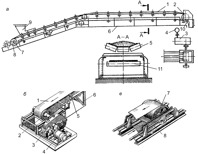
Figure 1 – The flowsheet
The tape is driven by frictional force occurring during the rotation of the driving drum 2. Pretension created through tensioning device 8 which is installed on the terminal idler drum or belt branches (vertical tensioner). Currently, almost all the mines conveyor lines are automated. Development of automation of mine conveyor lines over a long period by the need to reduce the complexity of managing and improving the safety of operation of conveyor transport. In connection with this widespread automated conveyor line management, technical essence of which is to centralize the management of processes start and stop conveyors, as well as providing automatic protection of the accident in case of emergencies [2].
3.2 Critical review of the prior art process automation conveyor transport
Automatic control system for conveyor lines SAUKL type.
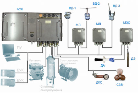
Figure 2 – The automatic control system type SAUKL
SAUKL equipment designed to automate mine and mine conveyor transport, consists of a set of remote control equipment, including control panel (PU), the adapter control unit (APU), communication line adapter (ALS) and a set of control equipment conveyor comprising conveyor control unit (CCU), linear modules (ML) module clogging by cuttings and sirens (FHI), the acoustic sensor (TA) and power supply (SP).
SAUKL equipment intended for:
gate,
excavator,
feeder);
AUC-1M complex automated control of pipelines, designed to control branched conveyor lines.
Apparatus AUC-1M performs the following functions:
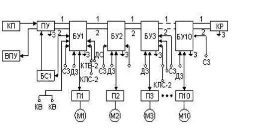
Figure 3 – Block diagram of the apparatus AUC-1M
The figure indicated: ПУ–remote control, ВПУ–remote device pointer, БО–control units, БКР–terminal block relay, ДС–speed sensor, КСЛ-2–control sensor gathering tape, КТВ-2–cable-rope switches, ДЗ–sensor clogging by cuttings.
Explosion protection equipment and intrinsically safe control circuits parameters allow for control, signalling, control of the conveyor line and telephone service for two isolated from each other naked wires and circuit land or with the help of three cores of control cable. Start the conveyor line by submitting a line control (wire 1 and 2) trigger polarity (+ on the wire 1, - on the wire 2). After the end of the starting process to switch polarity trigger labour (+ on the wire 2, - on the wire 1), the control relay BU second conveyor is fed through the relay contacts BU speed of the first conveyor. Thus, electromechanical interlock work performed subsequent conveyor depending on the work of the preceding pipeline. Disabling the conveyor line can be made by the operator by pressing Stop button on any unit or PU BU.
3.3 Rationale and development of automation systems branched conveyor line
Because jerking trunk conveyors operated the mines, often are not used to full capacity, and the proportion of idle, or close to regimes constitute an important part of the working time. Striving to improve the reliability and reduce the cost of LC resulted in the widespread use of these unregulated drive based on asynchronous motors with squirrel-cage rotor (BP). However, as the analysis of the factors determining the mode LC, fixed drive is not sufficiently effective. The reason is, first, the variable intensity of traffic coming into the pipeline, and secondly, the high rigidity of the mechanical characteristic of the drive AD. Fluctuations in the intensity Incoming cargo lead to a corresponding change in the load on the drive, which can vary quite widely.
The main problems to be solved in the course of the research can be summarized as follows:
1) Application of regulation of traffic through the use of storage systems (intermediate hoppers, conveyors) that provides adaptation intensity cargo arrives to the conditions of unregulated conveyor drive.
2) Application of speed control as part of the drive LK providing adaptation pipeline under varying traffic conditions (VFD, adjustable coupling, cascade control scheme BP wound rotor).
Cost-effective and reliable operation of the conveyor, it is due to the stability of the static load F. The latter, in turn, can be achieved by maintaining a predetermined level of relations between the intensity of the incoming traffic Q and belt speed V. In the absence of storage hopper, which is typical for the district, and also unbranched sections of main conveyor lines, freight is regarded as an independent disturbance. The only factor which can be influenced by the load of the drive (stabilized by the output value) is the speed (the manipulated variable) [3].
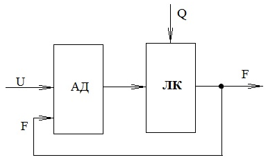
Figure 4 – Design scheme of the identified object
Depending on the meaning of the traffic volume at a constant traction speed is changed several times, thereby changing the engine load and, consequently, its sliding. Since the optimum sliding corresponds to the maximum power factor and efficiency, it is necessary to control the belt speed for optimum performance EP.
If there is no speed control, static moment resistance of the motor, depending on traffic, varies considerably, which adversely affects the reliability and efficiency of its engine power. If adjust the speed depending on the traffic you can achieve optimal energy performance values of the electric conveyor belt, as well as increase the life of the load-bearing body. It follows that the application of modulating linear tape speed, for example, using variable frequency drive, can reduce power consumption compared to an uncontrollable drive. As office automation equipment type SAUKL adopted. SAUKL equipment was selected as performed on the basis of a modern microprocessor, and also has modern facilities and communication standards. Intrinsic in SAUKL provides isolation of electrical circuits remote control, communication lines, telephone lines, line modules linear lines deadlock electrode sensor supply chains and electronic circuits, as well as the use of schemes to limit the power sparks possible by limiting the short-circuit current circuit.
As office automation equipment type SAUKL adopted. SAUKL equipment was selected as performed on the basis of a modern microprocessor, and also has modern facilities and communication standards. Intrinsic in SAUKL provides isolation of electrical circuits remote control, communication lines, telephone lines, line modules linear lines deadlock electrode sensor supply chains and electronic circuits, as well as the use of schemes to limit the power sparks possible by limiting the short-circuit current circuit [4].
To extend the functionality of equipment and SAUKL solve congestion conveyor drive and impractical economic developed using the microprocessor based device that will perform the function of controlling the speed of the conveyor line, depending on the incoming traffic on the tape. Block diagram is shown in Figure 5.
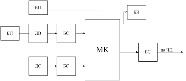
Figure 5 – Block diagram of control device and forming a predetermined speed
Figure 5 shows:
БП – power supply unit; БС – matching unit; ДВ
– weight sensor;
ДС – speed sensor; МК – microcontroller; БИ
– the display unit;
Device forming a predetermined speed (UFS) consists of sensor unit and the microprocessor of the signalling unit includes LCD display. Basis of the device is a microcontroller. Weight sensor is located in the previous pipeline, it enables faster response to changes in traffic. Using thin-film sensor weight, they are recommended for use in the mine. Signals from the speed sensor (via galvanic isolation) and a weight sensor (via current loop) shall be made to the analog input of the microcontroller. ADC module, which is included in its composition converts this information into binary code for further processing. Actual traffic is evaluated on the tape and comparing it with the set. Depending on the difference between these values generates a control signal which, via an RS-485 reaches its final destination the frequency converter is connected to the motor drive belt. Alignment of the signal generated from the RS-485 interface converter occurs through. To control the operation of the device is present in the liquid crystal display unit, which displays information about the speed and performance of the conveyor. The quantity of coal on the tape, ie incoming cargo weight is variable parameter, and speed-adjustable [6].

Figure 6 – Functional diagram of the device forming a predetermined speed (animation: 7 frames, iterval: 55 ms, size: 112 KB)
The adjustment range of conveyor speed is adjustable between 0,1 V to 1,0 V, where V rated speed. Speed control signal produced by UVB. At zero load tape speed it does not exceed 0.1 times the nominal. With an increase in traffic and the load level reaches above the set value is signaled to increase the speed of the tape. Tape speed will increase until the load level is below the set value. Due to feedback UFS–converter is the automatic maintenance of the standard load at a given level. UFS together with frequency converter must maintain the constancy of the ratio of cargo / speed.
Findings
Discussed how to automate assembly line consisting of three district and one of the main conveyor. Forming apparatus was developed predetermined belt speed, which enables smooth control of conveyor belt speed, by changing the drive speed of the conveyor, depending on the incoming conveyor belt depending on the incoming traffic. An optimum amount for his speed in order to provide optimal load drive conveyor and achieve more efficient energy and economic indicators. Was the expediency of this study, designed the structural, functional and circuit diagram UFS, mathematical modelling. The methods for safe and trouble-free operation UFS. Justified technical factors-economic feasibility of engineering solutions. That prove the feasibility of the developed device.
When writing this abstract master's work is not finished. Final completion: December 2014. The full text of the work and materials on the topic can be obtained from the author or his head after the specified date.
List of sourcesв
- Малиновский А. К. Автоматизированный электропривод машин и установок шахт и рудников: учебник для вузов / А. К. Малиновский. – М.: Недра, 1987. – 277 с.
- Шахмейстер Л. Г. Динамика грузопотоков и регулирование скорости ленточных конвейеров / Л. Г. Шахмейстер, В. Г. Дмитриев, А. К. Лобочева. – М.: Машиностроение, 1972. – 160 с.
- Полунин В. Т. Эффективность регулирования скорости шахтных конвейеров / В. Т. Полунин / Научные труды МГИ. – 1968. – № 53. – С. 87 – 95.
- Дмитриева В. В. Разработка и исследование системы автоматической стабилизации погонной нагрузки магистрального конвейера: дис. кандидата техн. наук: 05.13.06 / Дмитриева В. В. – М., 2005. – 162 c.
- Лукас В. А. Теория автоматического управления: учебник для вузов / В. А. Лукас. – М.: Недра, 1990. – 416 с.
- Справочник по автоматизации шахтного конвейерного транспорта / Н. И. Стадник В. Г. Ильюшенко С. И. Егоров и др. – К.: Техника, 1992. – 438 с.
