
ABSTRACT
The content
- Introduction
- 1 The actuality of the topic
- 2 Materials for the production of film
- 2.1 Requirements to insulating coatings
- 2.2 Classification of pipes’ coatings
- 2.2.1 Polyethylene coating
- 2.2.2 Polypropylene coatings
- 2.2.3 Combined belt-plastic coating
- 2.2.4 Epoxy pipes’ coatings
- 2.2.5 Glass-enamel pipes’ coatings
- 3 Description of the design of the worm extruder and production line
- 4 Overview of the working environment and conditions of operation of the extruder
- 5 Main problems in the operation of extruders. Causes and ways to remove them
- 6 Functional quality control of insulation works
- A list of references
Introduction
To minimize corrosion damage, the pipelines are protected with corrosion-resistant coatings. As the outer protective pipe coatings are the most widely used polymeric films manufactured by extrusion.
Production of pipes with coated outer surface of the polymeric protective film is one of the key innovations of industrial development in modern conditions of Donbass.
In this regard, in the present work are regarded the issues associated with the formulation of requirements for coatings of pipes, structures of coatings, describtion of the construction and working principle of the extruder, possible defects of the film.
1 The actuality of the topic
Processing of raw material by extrusion provides a large volume of production, variety of products and a high economic benefits, due primarily to the fact that the use of the extruder permits to make the process continuous, easily controlled, a universal one by type of recyclable materials and finished products. This is the actual use for their production not only widespread raw materials and secondary raw materials in combination with various additives, which allows to obtain new products with unique sets of properties and patterns.
Thus, the detection of regularities of extrusion and justification of rational modes of operation of the extruder for the production of pipes with an outer protective layer is an urgent task that has important theoretical and economic value.
2 Materials for the production of film
2.1 Requirements to insulating coatings
To act the coatings as insulators, they should have the following properties [1–4]:
- waterproof, precluding the possibility of saturation of the pores of the coating of soil moisture and thereby preventing contact of the electrolyte with the protected surface of the pipe;
- good adhesion (sticking) of the coating to the surface of the insulated pipe, which prevents the peeling of the insulation of the local destruction of its integrity, and it also eliminates the penetration of the electrolyte under the coverage;
- continuity, as even the smallest porosity in the coating leads to the creation of electrolytic cells and the occurrence of corrosion processes;
- chemical resistance providing long-term operation of the coating in corrosive environments;
- electrochemical neutrality – individual components of the coating should not participate in the cathodic process, as this may lead to destruction of the insulation for electrochemical protection of metal structures;
- mechanical strength;
- thermal resistance, defined the required softening temperature, which is important in the isolation of
hot
objects, and the temperature of the onset of embrittlement, which is of great importance when carrying out insulation work in winter season; - dielectric properties determining the resistance to the passage of current, to prevent the formation of corrosive elements between the metal and the electrolyte and contributing to the economic effect of the application of cathodic protection;
- the lack of corrosion and chemical effects on the protected object;
- the possibility of mechanization of the process of applying an insulating coating both factory and in field conditions;
- efficiency (cost of insulation coating must be many times less than the cost of the protected object).
2.2 Classification of pipes’ coatings
For outdoor pipe insulation the most common are the following types of coatings:
- epoxy;
- polyethylene;
- polypropylene;
- the combined tape-polyethylene;
- glass-enamel.
2.2.1 Polyethylene coating
There are 4 possible structures pipe coatings:
- Plastic coating applied on bitumen mastic sublayer (GOST R 51164–98).
- Plastic coating applied on the insulating substrate on the basis of the adhesive polymer tape (GOST R 51164–98).
- Two-layer polyethylene coating of the adhesive sublayer based on hot-melt polymer composition and an outer plastic layer (GOST R 51164–98).
- Three-layer polyethylene coating, consisting of a layer of epoxy primer coating (primer), adhesive of polymeric sublayer and the outer plastic layer (GOST R 51164–98).
Pipes coated with extruded polyethylene hawe the following advantages [5]:
- increased maintenance-free service life of pipelines;
- high mechanical strength;
- coating’s quality does not depend on the ambient temperature;
- high rate of adhesion to the material of the pipes;
- high dielectric characteristics;
- wide temperature range of use (-50 °С to +80 °С).
2.2.2 Polypropylene coatings
Polypropylene coating has a high heat resistance, a high mechanical and impact strength, resistance to bursting and abrasion [6]. But it has one serious drawback – reduced frost resistance.
The main application of polypropylene coatings is corrosion protection of “hot” (up to 110–140 °С), marine and offshore pipelines.
2.2.3 Combined belt-plastic coating
ДFor corrosion protection of pipelines of small and medium diameters (up to 530 mm) is widely used combined belt combo-plastic coating. The main advantage of this coating lies in the possibility of application to the pipe both in the factory and in field conditions [7].
Temperature range of operation of pipelines with a combined coverage is from -20 to +40 °С, and the projected lifespan is 35–40 years.
2.2.4 Epoxy pipes’ coatings
Epoxy coatings are characterized by high heat resistance, high adhesion to steel excellent resistance to cathode disbandment, resistance to cutting, stripping and abrasive erosion. Pipes with epoxy coating can be stored under the open sky for a long time. The costs of applying epoxy coatings are significantly lower than the costs of polyethylene and polypropylene pipe coatings (energy-intensive extruders, systems of loading are excluded from technological lines consumption of insulating materials, etc.) [8].
The main disadvantages of epoxy coatings are not sufficiently high elasticity and low impact strength, especially in subzero temperatures, which greatly complicates the transportation of insulated pipes and the fulfillment of construction and installation works in field conditions.
This type of coating can be used in the construction of marine, offshore pipelines (including the manufacture of insulated and concreting pipes), when pipe-laying on sections of punctures under roads, when building with method of directional drilling.
2.2.5 Glass-enamel pipes’ coatings
Glass-enamel is a vitreous inorganic frozen mass obtained by melting consisting mainly of oxides and deposited on the metal in one or more layers.
Glass-enamel factory coatings are applied for protection of pipelines from underground and atmospheric corrosion [9].
Analysis of submissions protective coatings shows that no one material fully meet all requirements, so for isolation certain materials are chosen that meet requirements, the most characteristic for the considered conditions of construction and operation of the pipeline.
In the work, taking into account the increased demands on the quality of the coating of underground pipelines, the availability of coating materials, adaptability and relatively low cost of the coating is selected three-layer polyethylene coating, consisting of a layer of epoxy primer (primer) adhesion of polymeric sub layer and the outer plastic layer (GOST R 51164–98).
3 Description of the design of the worm extruder and production line
The application of exterior protective coatings for pipes is carried out by using the equipment of mechanized production lines. The composition of these lines includes:
- roller conveyors;
- the transfer units of pipes;
- sites of cleaning (shot blasting cleaning or shot blasting jet machines);
- furnaces of production process heating pipes (induction or gas);
- unit of powder spraying epoxy primer;
- two extruders, one for application of the adhesive sub layer and the second for outer coating layer;
- the packer devices;
- cameras of water cooling insulated pipes;
- equipment for quality control of coating.
In the design of three-layer protective coating the first layer of epoxy primer is applied on the cleaned and heated to the required temperature of the pipe by spraying, then the extruded melts of the hot melt adhesive composition and polyethylene are consistently applied [5].
A structural diagram of a line drawing by extrusion of the outer plastic layer on the prepared pipes is shown in figure 1.
Figure 1 is a structural diagram of a technological line of application of the outer polyethylene layer on pipes by extrusion
(animation: 10 frames, 5 cycles of repeating, 160 kilobytes)
The barrel 13 of the extruder conventionally is divided on lengthwise into three zones:
- 1st zone of reception of raw materials;
- 2nd zone of plasticization (melting);
- 3rd zone of homogenization.
A recyclable plastic material is fed from the hopper 12 into the 1st zone of reception of raw material and with the help of screw 8 is moved along the body. When the material moves it is compacted by reducing the depth of cutting of the screw [10].
In the zone of the plasticizing material is melted in the spots of contact with the surface of the housing due to heat transfer from the heated wall, and the heat arising from the friction of polymer pellets on the screw and the casing wall. The heating of the walls of the housing is carried by electric resistance heaters 10. Temperature control along the length of the hull is carried out with the air fans 15 inside removable protective fences 9 of the housing and the portion of the hull near the feed opening is cooled by water which passes through the channels 11 of the housing. Rotational movement of the screw 8 is informed by the actuator consisting of a motor and two-stage reducer 14. Regulation of frequency of rotation of the screw is effected by changing the frequency of rotation of the rotor of the electric motor using thyristor frequency Converter.
Grid 7 or a package of multiple grids is set on the output material from the body and creates the resistance needed to increase the pressure in the zones of the plasticizing and homogenization. The pressed material forms a plug tube (in the reception zone material is solid, in the plasticizing zone – melting). The pressure in the plug rises to a value sufficient to overcome the resistance of the grids 7 and the molding profile.
At the beginning of the 3rd zone homogenization the material consists of solid and molten particles. By the end of the 3rd zone of the raw material becomes completely homogeneous molten mass. At the outlet from the housing 13 of the extruder the polymer melt through the transferring unit 6 is fed to a slot die head 5 and is forced through it.
At the exit of the flat die head 5 film passes around the guide roller 4 and is applied to the surface of the rotating and translationally moving along the line of the pipe 2 by spiral winding with pressing to the pipe elastic roller 3. The film should have a smooth continuous surface without bubbles, stripes, corrugations and inclusions [10].
Insulated pipes on the roller conveyor 1 enter the cooling tunnel. Then the ends are stripped and with the help of transfer units pipes are served on the rack of finished products.
4 Overview of the working environment and conditions of operation of the extruder
Equipment for applying a plastic coating on the pipes is not flammable and explosive, however, it should not be installed in zones with potentially explosive surroundings, as in the presentation to open flame polyethylene lights up without an explosion and flame burns smoking with the formation of the melt and the release of gaseous products of combustion. In conditions of normal operation vibration of equipment process line is absent [11].
Risk factors arising from work of equipment:
- unprotected moving parts of equipment;
- heated pipes, transported by the conveyor;
- dust, which consists of substances that can cause corrosion;
- toxic fumes.
Based on the foregoing, the suppliers of raw materials, additives and consumables must provide all information related to their products, potential hazards and the safety measures that must be followed during storage and use.
5 Main problems in the operation of extruders. Causes and ways to remove them
Rational modes of operation of the extruder during film production to protect pipelines against corrosion depend on the quality requirements of the resulting polymer film.
The main adjustable parameters are:
- pressure;
- temperature;
- screw rotation speed.
For timely detection and elimination of defects it is necessary to measure the following parameters:
- pressure in the head;
- frequency of rotation of the screw;
- the temperature of the melt in the head;
- the temperature distribution along the length of the housing;
- the cooling rate of each zone of the extruder;
- the speed of the film;
- the geometric dimensions of the film;
- the temperature of the water.
The work of extrusion line is also influenced by external conditions:
- the ambient temperature;
- air convection;
- voltage fluctuations in the mains.
Mechanical changes in the extruder (the problems associated with the equipment) involve changes in the technological process and can be associated with various systems of the extruder:
- with the drive system (manifest in the change of screw speed);
- system of loading raw material into the extruder;
- system of heating and cooling.
Variations in production rate of the extruder is the most common problem during extrusion, because it can be caused by a variety of reasons, chief among which are [4, 13]:
- uneven material feed from the hopper and its subsequent transportation in the extruder;
- insufficient capacity of the heaters of the extruder for melting the polymer;
- insufficient temperature of the melt in the head;
- the low temperature of the working cylinder;
- discontinuity of the film;
- incorrectly selected screw speed;
- fluctuations of pressure in the head.
Major violations of the mode of operation of the extruder [13]:
- capture of air;
- forming of voids in the extruder;
- the appearance of a gel-like inclusions;
- the appearance of longitudinal stripes and scratches;
- foreign matters;
- the darkening of the surface;
- lackluster surface;
- the appearance of a rough surface;
- the deviation of the film thickness (more or less) of the set value;
- low mechanical strength of the film;
- the folds and wrinkles on the film.
Incomplete equipment of the extrusion line and, in particular, the extruder with control equipment can greatly hinder the rapid and accurate detection of faults.
6 Functional quality control of insulation works
Quality control of the insolating coatings is carried out in the production process. The suitability of insulation materials for pipe insulation is determined by the technical supervision service [1, 3]. Thus is controlled the correctness of the technological process of heating of bituminous materials, compliance of physical-mechanical properties of raw materials and mastics to the requirements of GOST and SNiP. To do this at least once a day one should spend the selection of a control sample of mastic to determine the softening temperature.
For operational control of the extrusion process, and improving the quality of the final products it becomes necessary to determine the physical and mechanical properties of a particular batch of processed material, in particular the coefficient of external friction.
Known devices for determining the coefficient of external friction of granular materials when moving relative to the solid surface [14] do not take into account frictional forces of the material of the wall of the matrix, which leads to lowing of accuracy. This disadvantage is eliminated in the device, developed at the Department of machines and apparatuses of chemical productions DonNTU [15].
Structural scheme of the device is shown in figure 2.
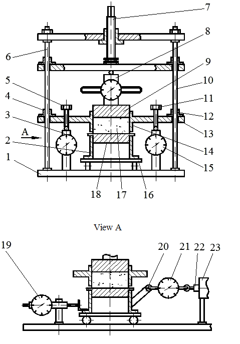
Figure 2 – structural diagram of the device for determining the coefficient of external friction of the granular material on the working surfaces of the extruder
The unit is mounted on the base plate 1 and contains two matrices. Lower matrix 2 is mounted on the trolley 16 and the top one 14 is secured to the flange 13. The flange 13 is mounted on two dynamometers 3 and 15. Bars with strain gauge transducers can be used instead of dynamometers.
To the bottom of the matrix 2 is attached the sample 18 with the investigated surface facing towards the top of the matrix 14. The investigated granular material 17 is loaded into the upper cavity of the matrix. The clearance between the upper matrix and the inspected surface is regulated by screws 5 and 11. Sleeves 4 and 12, which are moved along the guide posts 6 and 10 are attached to the flange 13 to prevent misalignment of the upper matrix 14.
The force on the punch 9 and the granular material is created by the screw 7 and is measured by a dynamometer 8. The forces of friction of the wall of the upper matrix are registered by dynamometers 3 and 15, and are considered in determination of the medium pressure investigated material on the investigated sample surface 18.
Moving the bottom of the matrix is performed by the mechanism, where actuating link is the rod 22 of the screw gear 23.
The force required to move the truck with the lower matrix 2 is measured by a dynamometer tension 21, which is fastened to the thrust 20 the bottom matrix 2. Placing traction 20 should be such that the line of action of the efforts of the movement was in the plane of shear of the investigated granular material relatively hard surface.
To register the start of moving the bottom matrix 2 to the support plate 1 a micrometer dial gauge 19 is mounted.
The thickness of the protective coating is determined with the help of ultrasonic thickness gages in the process of fulfilmend of insulation works through each 100 m of pipes, in places of a stop of insulation machine, no less than in four points on the circumference of the pipe or vessel and at each fitting.
The continuity of the coating is controlled by spark detector.
The quality of the protective coating with acceptance tests is checked every 500 m and also selectively according to customer's requirement.
The coating adhesion of the mastic to the surface of the protected object is controlled by adhesion device or manually by cut through the protective coating at an angle of 45-50° with a separation vertex of the angle cut.
When depositing the protective coating of the pipeline to the customers are presented: passports for each batch of materials or the results of laboratory testing of materials; laboratory analyses of samples of bituminous mastics; journals of work; the acts of checking the quality of the protective coating. Quality control of insulation coating the finished sections of the pipeline and filled with solid ones is carried out by the cathodic polarization.
When writing this abstract master's work has not been finished yet. Final completion: January 2016. The full text of work and materials on the topic can be obtained from the author after the mentioned date.
A list of references
- GOST R 51164-98 Steel Pipe Mains. General Requirements for Corrosion Protection.
- GOST 9.602-2005 Underground Structures. General Requirements for Corrosion Protection.
- Corrosion Protection of Pipelines and Tanks/ M. V. Kuznetsov, V. F. Novoselov, P. I. Chugunov and others – M.: Nedra, 1992. – 238 p.
- Kryzhanovsky, V. K., Kerber, M. L., V. V. Burlov, Primachenko A. D. the Manufacture of Products from Polymeric Materials. E – S-P: Occupation, 2008. – 460 p.
- THE 1390-001-86695843-08. Steel tubes with a diameter of 57-1420 with outer two-layer and three-layer polyethylene coating.
- THE 1394-010-17213088-03. Steel tubes with a diameter of 57-1420 with an outer coating based on extruded polypropylene for construction of trunk oil pipelines.
- THE 1390-014-05111644-98. Pipe diameter 57-530 mm combined with outer band with a plastic coating.
- THE 1390-014-86695843-2011. Pipes and parts of pipelines with outer steel double-layer epoxy anti-corrosion coating.
- THE 1396-001-12617190-95. Nodes of steel pipelines with two-sided glass-enamel coating. Technical conditions.
- Technological instruction special process of external anti-corrosion coating of pipes, 2014. – 14 p.
- User manual extruders TR.100 and TR.200, revision 1, dated 26.10.2006. – 55 p.
- Lapshin V. V. fundamentals of processing of thermoplastics by injection molding. - M.: Chemistry, 1974. – 271 p., ill.
- The problem of identifying and eliminating possible defects in the process of obtaining products from thermoplastic materials: textbook /A. N. Garden, T. R. Debordieu, O. N. Kuznetsova, O. V. Stoyanov. – Kazan: Publishing house of Kazan. state Indus. University press, 2009. – 123 p.
- Bulychev, V. G. The mechanics of dispersed soils. - M.: Stroiizdat, 1974. – 227 p., ill.
- A. S. USSR №846637. Ostapenko M. A., Rasskazov N. And., Fedorenko A. D. instrument to study the shear resistance of soils and granular materials. B. I. № 18, 1981.